Land Rover Discovery. Manual - part 156


  Index      Land Rover     Land Rover Discovery - service 1995-1996 year


Search            


Content   ..  154  155  156  157   ..


Land Rover Discovery. Manual - part 156


BRAKES

21

REPAIR

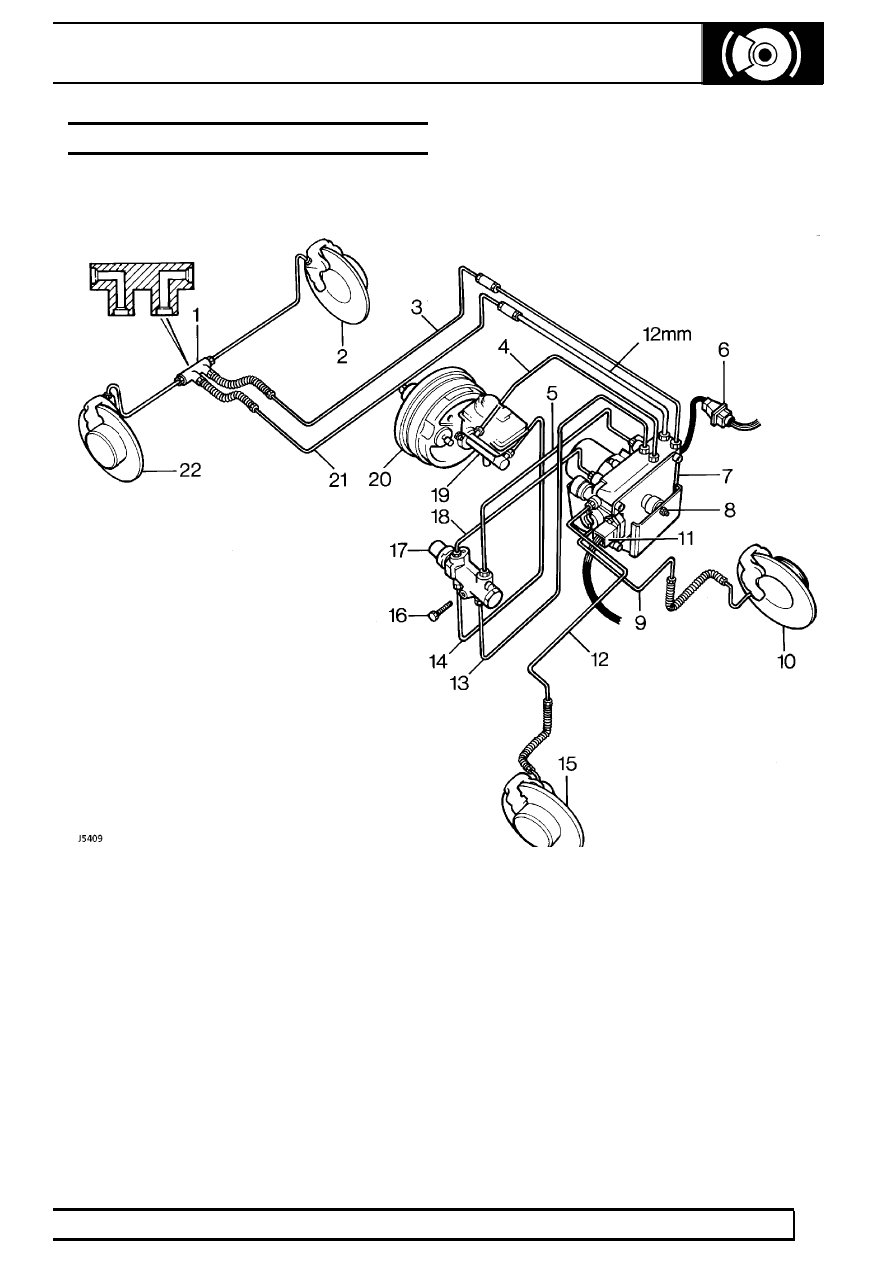
BRAKE COMPONENTS ABS

Left hand drive shown. On right hand drive vehicles the master cylinder and servo unit only move
position.

KEY

1. Connector-double elbow
2. Rear left brake
3. Modulator to rear left brake
4. Modulator to master cylinder
5. Modulator to pressure reducing valve upper
6. Electrical connection
7. Modulator unit
8. Nut, mounting bush and cup
9. Modulator to front left brake

10. Front left brake
11. Electrical connection

12. Modulator to front right brake
13. Modulator to pressure reducing valve lower
14. Master cylinder to pressure reducing valve lower
15. Front right brake
16. Bolt
17. Pressure reducing valve
18. Modulator to pressure reducing valve upper
19. Master cylinder
20. Servo unit
21. Modulator to rear right brake
22. Rear right brake

70

BRAKES

22

REPAIR

MODULATOR UNIT

Service repair no - 70.65.45

WARNING: New modulator units are
supplied in a shock absorbing pack
marked with a use by date. The new

modulator will contain hydraulic brake fluid within
the valve block and all ports plugged.

Modulator units must be handled with care the
following must be avoided:- any impact, use of
compressed air on any of the hydraulic ports,
removing plugs to connection ports before fitting
unit.

Remove

1. Refer to the illustration of brake components

ABS. For details of modulator unit and hydraulic
pipe connections to it.

See Brake

Components ABS

2. Refer to general brake service practice.

See

General Brake Service Practice

3. Check new modulator unit is packaged in

accordance with the WARNING above.

4. Disconnect battery negative lead.
5. Remove the two electrical plugs.
6. Identify 8 pipe to modulator connections for

correct reassembly.

7. Disconnect 8 pipe unions.
8. Remove nuts securing modulator to mounting

bracket.

9. Remove modulator unit.

10. Remove mounting bushes and cup.

Refit

11. Fit mounting bushes and cup to new modulator.
12. Fit modulator unit to mounting bracket.
13. Fit 8 pipes to modulator connections. Pipes

must be connected to correct port. Tighten to
15Nm.

14. Bleed the complete hydraulic system.

See

Brake System Bleed

15. Check system function using the ’Testbook’

diagnostics

16. Test operation of brakes.

ELECTRONIC CONTROL UNIT ABS

Service repair no - 70.65.01

Remove

For location of the ECU.

See Description and

operation, ABS Components

1. Disconnect battery negative lead.
2. Remove retaining bolt and lower alarm system

ECU and relay mounting bracket into passenger
footwell.

3. Remove two screws and detach ECU complete

with harness plug from mounting bracket.

4. Release ECU plug retaining clip.
5. Move plug in direction of arrow and release

hooked end of plug from retaining post.

Refit

6. Reconnect ECU harness plug ensuring that it is

firmly located and retaining clip secures plug.

7. Reverse removal procedure.

BRAKES

1

SPECIFICATIONS, TORQUE

TORQUE VALUES

NOTE: Torque wrenches should be regularly checked for accuracy to ensure that all fixings are
tightened to the correct torque.

Nm

Brakes
Brake pipe connections to:

- Modulator unit

15

.................................................................................

- Brake calipers

15

.................................................................................

- Master cylinder

15

................................................................................

Jump hoses to calipers

15

..............................................................................

Bleed screws

15

..............................................................................................

Brake caliper to swivel pin housing

82

............................................................

Servo assembly to pedal box

26

.....................................................................

Master cylinder to servo

26

.............................................................................

BRAKES

1

SERVICE TOOLS

BRAKE SERVICE TOOLS

LRT-70-500

Brake piston compressor

18G 672


Content   ..  154  155  156  157   ..