Land Rover Discovery. Manual - part 147
64
REAR SUSPENSION
2
REPAIR
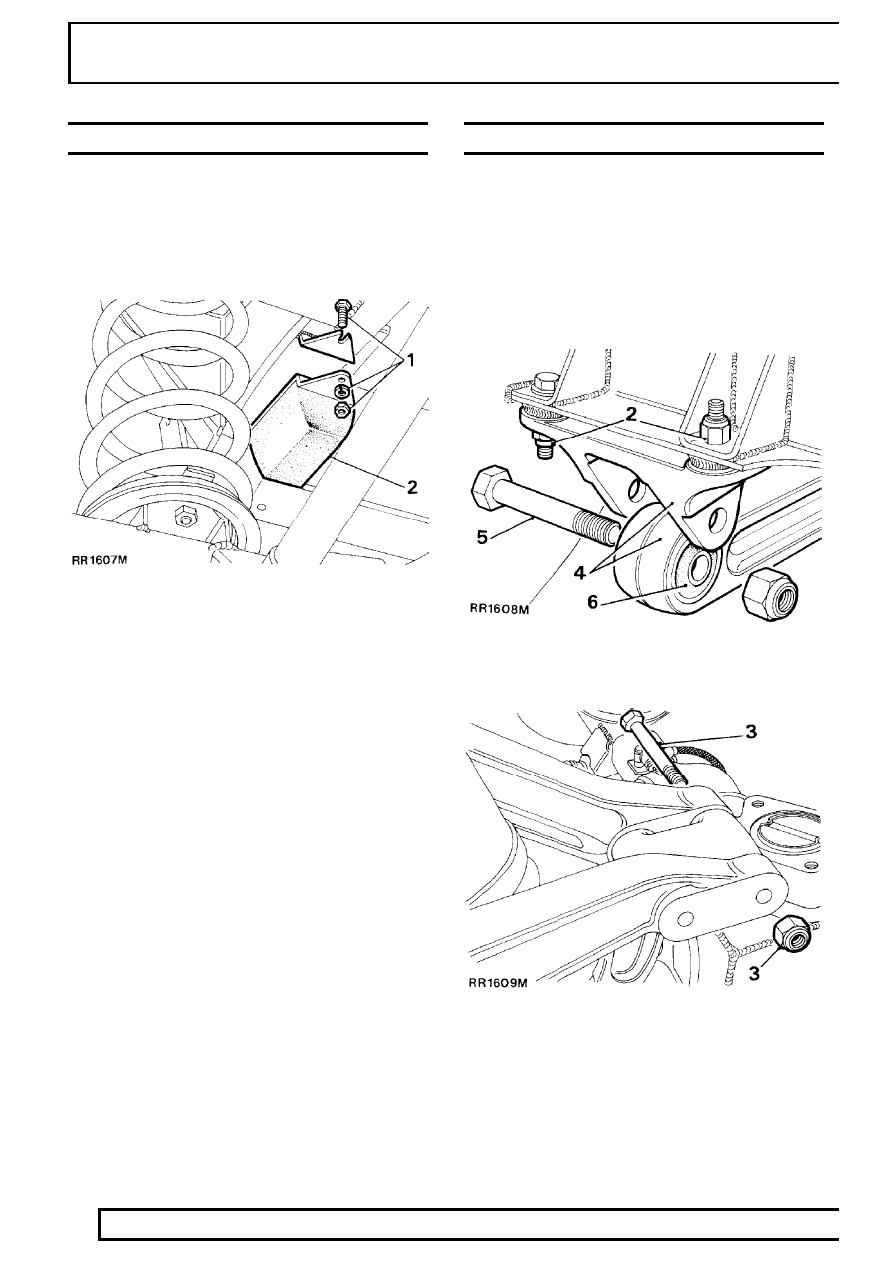
BUMP STOP
Service repair no - 64.30.15.
Remove
1. Remove fixings.
2. Remove bump stop.
Refit
3. Position bolts in slots in bracket.
4. Fit bump stop secure with washer and nuts.
SUSPENSION LINK UPPER
Service repair no - 64.35.44.
Remove
1. Support rear of chassis on stands, allow axle to
hang freely.
2. Remove fixings, upper link bracket to frame.
3. Remove fixings, upper links to pivot bracket.
4. Remove upper link complete with frame bracket.
5. Remove bolt.
6. Separate link from bracket.