Land Rover Discovery. Manual - part 142


  Index      Land Rover     Land Rover Discovery - service 1995-1996 year


Search            


Content   ..  140  141  142  143   ..


Land Rover Discovery. Manual - part 142


57

STEERING

6

OVERHAUL

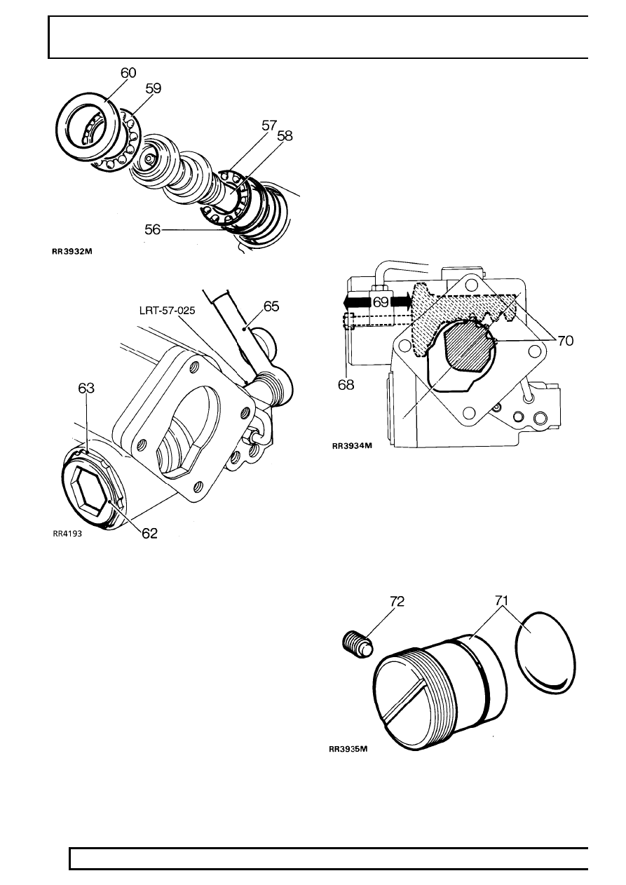
61. Fit new worm adjuster sealing ring.

62. Loosely screw adjuster into casing.
63. Fit locknut, do not tighten.
64. Turn in worm adjuster until end float is almost

eliminated. Ensure bearing cages are seated
correctly.

65. Measure maximum rolling torque of valve and

worm assembly, using a torque wrench and
spline socket LRT-57-025.

66. Turn in worm adjuster while rotating shaft to

increase figure measured in instruction 65. to
0.56 Nm.

67. Back off worm adjuster 1/4 turn. Turn in worm

adjuster to increase reading at 65. by 0.21 - 0.34
Nm with locknut tight,

100 Nm. Use worm

adjusting wrench LRT-57-006 and locknut
wrench LRT-57-028.

Fitting rack and piston

68. Screw slave bolt into piston to aid assembly.
69. Fit piston and rack so piston is 70 mm from outer

end of bore.

Fitting sector shaft

70. Fit sector shaft using seal saver LRT-57-021.

Align roller with cut out in casing - see
RR3934M. Push in sector shaft while rotating
input shaft to allow sector roller to engage worm.

Fitting rack adjuster

71. Fit rack adjuster and thrust pad to engage rack.

Back off half turn on adjuster.

72. Loosely fit new nylon pad and adjuster set screw

assembly.

STEERING

7

OVERHAUL

Fitting sector shaft cover

73. Fit new sealing ring to cover.
74. Align cover with casing.
75. Screw cover assembly fully on to sector shaft

adjuster screw.

76. If necessary back off sector shaft adjuster screw.

Tap cover in place to allow cover to joint fully
with casing.

NOTE: Before tightening fixings, rotate
input shaft to ensure sector shaft roller is
free to move in valve worm. If initial

resistance is left, turn adjuster screw
approximately two turns in a clockwise direction.

77. Fit cover bolts. Tighten to

75 Nm.

Fitting cylinder cover

78. Fit new square section seal to cover.
79. Remove slave bolt fitted at instruction 68. Press

cover into cylinder just to clear retainer ring
groove.

80. Fit retaining ring to groove with one end of ring

positioned 12 mm from extractor hole.

Adjusting sector shaft

NOTE: Refit drop arm and tighten nut
sufficiently to ensure that no backlash
exists between drop arm and sector shaft.

81. To set worm on centre, rotate input shaft to full

inner-lock (full right lock for a left hand drive
vehicle, full left lock for a right hand drive
vehicle). Rotate input shaft back towards centre
two full turns.

82. The box is now on centre and can be adjusted.

57

STEERING

8

OVERHAUL

83. Hold input shaft and rock drop arm to establish

backlash is present. Continue rocking and slowly
turn sector shaft adjusting screw clockwise.
Continue rotating adjuster screw until backlash
has almost been eliminated.

84. Refit locknut and tighten.

NOTE: It is important steering box is
centralised before any adjustments are
made.

85. Check maximum rolling torque one and a quarter

turns either side of centre position, using a
torque wrench and spline socket LRT-57-025.
Rotate adjuster screw to obtain across centre
torque of 0.34 Nm plus torque figure at one and
a quarter turns. Tighten adjuster locknut to

60

Nm.

Adjusting rack adjuster.

86. Turn in rack adjuster to increase figure

measured in instruction 85. by 0.23 - 0.34 Nm.
The final figure may be less, but must not
exceed 1.35 Nm.

87. Lock rack adjuster in position with grub screw.

Tighten to

5 Nm.

Torque peak check

With input shaft rotated from lock to lock, rolling
torque figures should be greatest across centre
position and equally disposed about centre position.

The condition depends on value of shimming fitted
between valve and worm assembly inner bearing cup
and casing. The original shim washer value will give
correct torque peak position unless major components
have been replaced.

Procedure

88. With input coupling shaft toward the operator,

turn shaft fully counter-clockwise.

89. Check torque figures obtained from lock to lock

using torque wrench and spline socket
LRT-57-025.

90. Check also for equal engagement either side of

centre.

Adjustments

91. Note where greatest figures are recorded

relative to steering position.If greatest figures are
not recorded across centre of travel (steering
straight-ahead), adjust as follows:

If torque peak occurs before centre position, add to
shim washer value; if torque peak occurs after centre
position, subtract from shim washer value,

refer to

fitting valve and worm assembly .

Shim washers are available as follows:
0.03mm, 0.07mm, 0.12mm and 0.24mm.

NOTE: Adjustment of 0.07mm to shim
value will move torque peak area by 1/4
turn on the shaft.

CAUTION: When reshimming valve and
worm, extreme caution must be exercised
to prevent seal damage during

reassembly.

STEERING

9

OVERHAUL

Input shaft oil seal

92. Fit seal, lip side first, into housing. Use seal

saver LRT-57-016 and seal installer
LRT-57-026. Note that seal is fitted to a depth of
4.75 - 5.00 mm from face of box.

93. Secure seal with circlip.
94. Smear inner lip of dirt excluder with PTFE

grease. Fit dirt excluder using LRT-57-027.
When fitted correctly outer shoulder of excluder
is 4.00 - 4.50 mm from face of box, dimension X
in RR3941M.

95. Remove drop arm. Smear inner lip of dirt

excluder with PTFE grease and refit, ensuring
outer lip is flush with casing.

96. With input shaft on centre, line up centralising

holes in drop arm and steering box see inset in
RR3940M. Fit drop arm to steering box using a
new tab washer. Tighten to

176 Nm, bend over

tab.

97. Fit steering box.

See Repair, Power Steering

Box


Content   ..  140  141  142  143   ..