Land Rover Discovery. Manual - part 110


  Index      Land Rover     Land Rover Discovery - service 1995-1996 year


Search            


Content   ..  108  109  110  111   ..


Land Rover Discovery. Manual - part 110


44

AUTOMATIC GEARBOX

2

REPAIR

1. Site vehicle on a four post ramp [hoist].
2. Disconnect battery negative lead.
3. Remove fan cowl securing screws and release

cowl from radiator.

4. Loosen securing clip and disconnect air flow

hose from plenum chamber.

5. Disconnect stepper motor hose from top of

plenum chamber.

6. Disconnect kickdown cable from throttle linkage

and release from clipping.

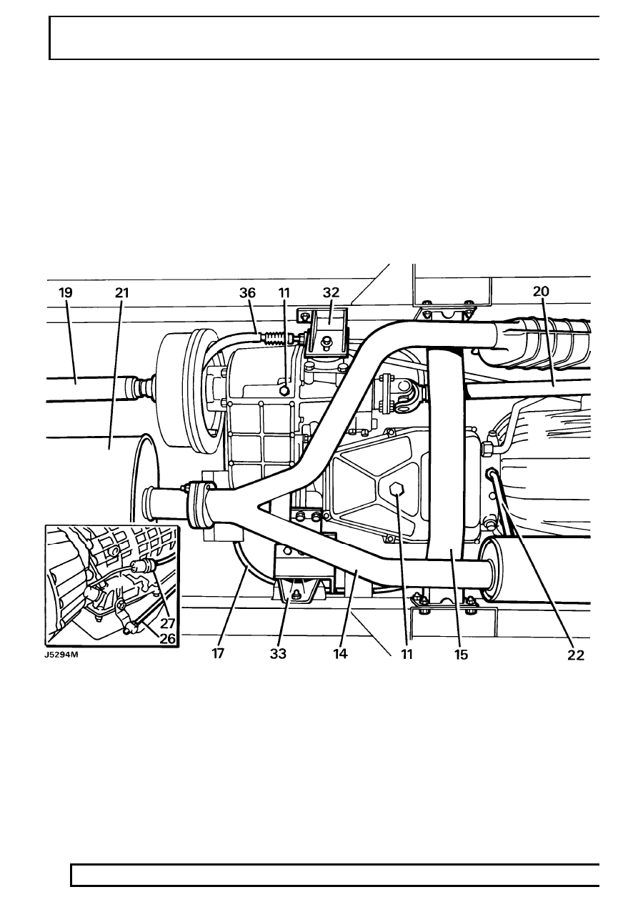
7. Release two gearbox breather pipes from clip

located on lifting eye at rear of right hand
cylinder head.

8. Remove dipstick from main gearbox oil filler

tube.

9. Working inside vehicle detach transfer gear lever

gaiter from console, unscrew knob and withdraw
gaiter and knob.

10. Raise vehicle on ramp [hoist].

11. Remove drain plugs and drain oil from transfer

gearbox and main gearbox. Refit plugs.

12. Detach heat shield at front exhaust pipe to

manifold.

13. Disconnect electrics to Lambda sensors.
14. Remove catalytic converter assembly.
15. Remove chassis cross-member from under

gearbox.

16. Remove heat shield from speedometer cable at

transfer gearbox.

17. Remove clamp and disconnect speedometer

cable from transfer gearbox. Tie cable to one
side.

18. Mark for reassembly propeller shaft to transfer

gearbox mating flanges.

ZF

3

REPAIR

19. Disconnect rear propeller shaft to output flange,

and tie to one side.

20. Repeat instructions 18 and 19 on front propeller

shaft to main gearbox.

21. Remove bolts retaining silencer front and rear

securing brackets and tie silencer to one side.

22. Disconnect oil cooler feed and return pipes from

bottom and side of main gearbox.

23. Release cooler pipes from clamp at engine sump

and remove distance piece.

24. Blank pipe ends and unions.
25. Move oil cooler pipes clear of transmission and

tie aside.

26. Disconnect selector cable from operating lever.
27. Disconnect inhibitor switch at multiplug.
28. Attach adaptor plate to hoist.
29. Remove two bolts from transfer gearbox rear

cover.

30. Raise hoist to align adaptor plate with transfer

gearbox and transmission. Secure to transfer
gearbox at rear cover with two bolts removed.

31. Adjust hoist to take weight of transmission.
32. Remove nuts and bolts securing right transfer

gearbox mounting bracket to chassis.

33. Repeat for the left mounting bracket. Removal of

these fixings will also free speedometer
transducer bracket

34. Remove right side mounting bracket to flexible

mounting rubber retaining nut.

35. Lower hoist until rear brake drum clears

passenger footwell. Check engine does not
crush any components while lowering.

36. Remove clip and clevis pin from park brake

lever.

37. Remove clip securing outer brake cable
38. The park brake cable is now free.
39. Disconnect leads from transfer gearbox

temperature sensor and differential lock warning
light switch.

40. Remove ties securing breather pipes to harness.
41. Remove bell housing access plate complete with

gasket.

42. Rotate engine, using crankshaft pulley, until two

access holes are visible in drive plate/ring gear
assembly through bell housing bottom cover
opening.

43. Identify an access hole and bolt hole to aid

reassembly.

44. Remove bolts securing drive plate to convertor

through access holes.

45. Rotate crankshaft half turn to access and

remove remaining bolts.

46. Disconnect oil dipstick tube at main gearbox.
47. Remove bolt at bell housing and detach dipstick

tube. Blank pipe end and union.

48. Position hoist jack channel under engine and

support using a wooden block.

49. Remove bell housing to engine securing bolts,

also detach harness bracket from bell housing.

50. Ease transmission rearwards to allow access to

secure torque converter in bell housing.

51. Lower hoist and complete removal of

transmission.

Refit

52. Ensure torque converter is retained in bell

housing.

53. Secure transmission to adaptor plate on lifting

hoist.

54. Raise hoist and locate transmission with engine.
55. Remove torque converter retainer.
56. Complete attachment of transmission to engine

and fit bell housing bolts. Fit the dipstick tube
bracket and harness bracket to their respective
bolts.

57. Complete refitting by reversing removal

procedure. Note the following important points.

58. Drive plate to torque converter bolts are to be

coated with Loctite 290 prior to assembly.

59. Refill transfer and main gearboxes with correct

grade oil.

See LUBRICANTS, FLUIDS AND

CAPACITIES, Information, Recommended
Lubricants and Fluids

60. Check operation of parking brake and adjust as

necessary.

See SECTION 10, Maintenance,

Vehicle Interior

44

AUTOMATIC GEARBOX

4

REPAIR

LT230T TRANSFER GEARBOX WITH AUTOMATIC
GEARBOX ASSEMBLY - Tdi

Service repair no - 44.20.04

Removal from Tdi engine

The assembled transfer gearbox, automatic gearbox
and torque converter is removed from underneath the
vehicle. Use a transmission hoist with an adaptor
plate for securing the assembly to the hoist.

WARNING: When using a transmission
hoist it is essential to follow the hoist
manufacturer’s instructions.

ZF

5

REPAIR

Remove

1. Select low range with transfer gear lever.
2. Remove knob and gaiter from transfer gear

lever.

3. Disconnect battery terminals.
4. Remove insulation pad from rocker cover and

inlet manifold.

5. On LH drive vehicles only, disconnect multi-plug

from top of brake fluid reservoir.

6. Release electrical harness from clips along top

of bulkhead and pull over to one side.

7. Remove bolt securing transfer and main gearbox

breather pipe clip to rear of cylinder head.

8. Disconnect kick down cable at fuel injection

pump.

9. Drain coolant from cooling system.

10. Disconnect top hose from radiator.
11. Disconnect turbo charger hose from inter-cooler.
12. Remove starter heat shield.


Content   ..  108  109  110  111   ..