Land Rover Discovery. Manual - part 101


  Index      Land Rover     Land Rover Discovery - service 1995-1996 year


Search            


Content   ..  99  100  101  102   ..


Land Rover Discovery. Manual - part 101


R380

1

REPAIR

R380 MANUAL GEARBOX

Service repair no - 37.20.02

Remove

WARNING: Where the use of a
transmission hoist is necessary, it is
absolutely essential to follow the

manufacturer’s instructions to ensure safe and
effective use of equipment.

1. Install vehicle on a ramp [hoist].
2. Disconnect battery earth lead.
3. Remove centre console.

See CHASSIS AND

BODY, Repair, Centre Console

4. Remove sound insulation from top of

transmission tunnel.

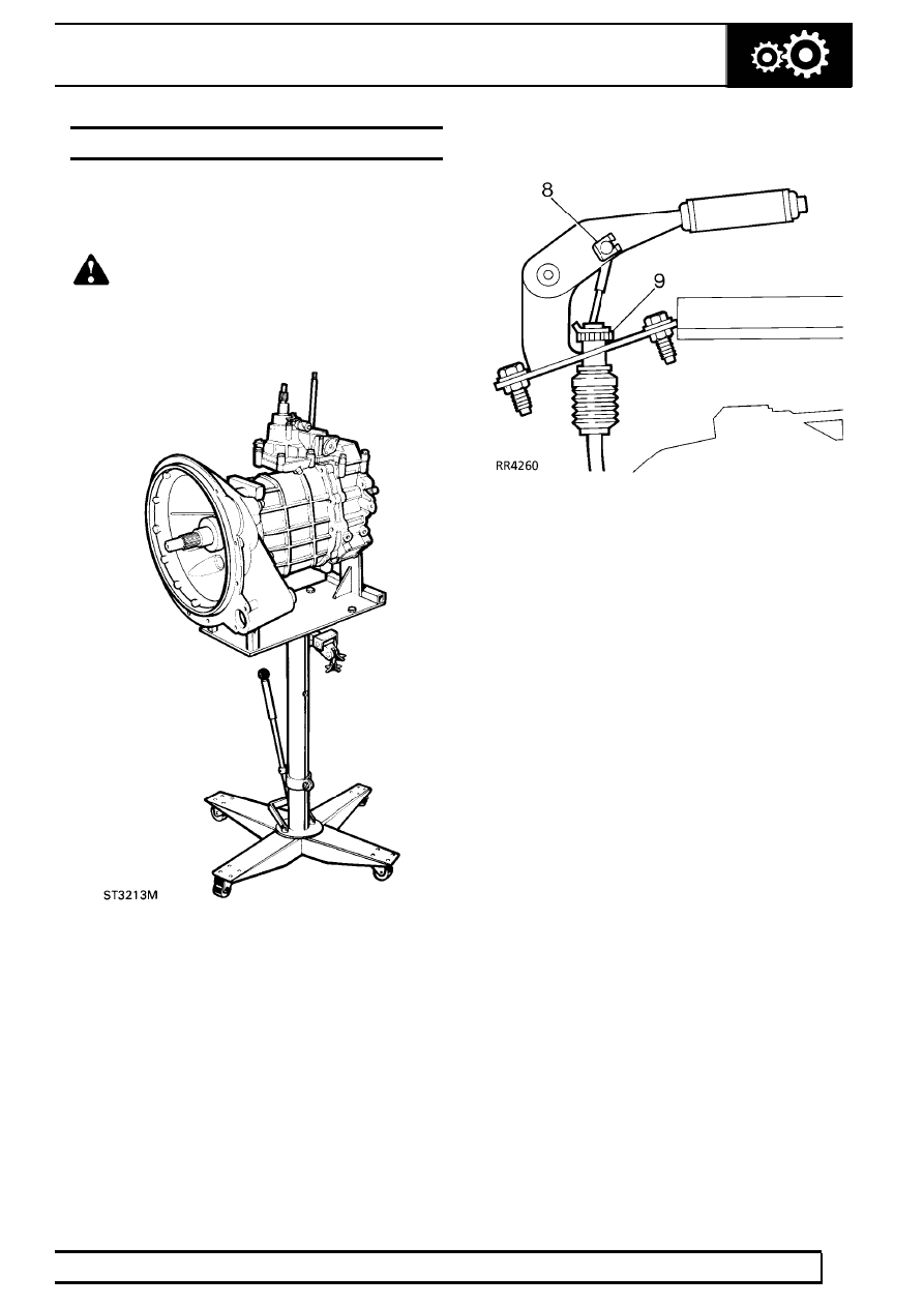
5. Remove bolt and remove upper gear lever.
6. Remove screws securing gear selector lever and

high/low selector lever draft excluders.

7. Remove draft excluder clamp rings.

8. Remove handbrake cable clevis pin clip and

clevis pin.

9. Remove ’C’ clip and cable adjuster.

10. Select low range to prevent gear lever fouling

tunnel when removing gearbox.

11. Remove bolt securing gearbox breather pipe clip

to cylinder block.

12. Remove bolts securing fan cowl to radiator.
13. Release fan cowl from radiator and lay over fan

blades.

14. Raise ramp [hoist].
15. Drain oil from main gearbox and transfer

gearbox.

See SECTION 10, Maintenance,

Under Vehicle Maintenance

16. Remove exhaust front pipe(s).

See MANIFOLD

AND EXHAUST SYSTEM, Repair, Exhaust
System Complete

17. Release intermediate exhaust pipe(s) from

mountings and tie aside.

18. Remove bolts securing clutch slave cylinder.
19. Release slave cylinder from clutch housing and

collect spacer.

20. Mark propeller shaft drive flange relationships for

reassembly.

21. Disconnect front and rear propeller shafts from

transfer gearbox. Tie shafts aside.

22. Remove clamp and disconnect speedometer

cable from transfer gearbox.

23. Release handbrake cable from transmission

tunnel.

24. Temporarily support transmission in a way which

enables the crossmember to be removed and a
hoist cradle to be fitted.

37

MANUAL GEARBOX

2

REPAIR

25. Remove nuts and bolts securing transmission

cross-member to chassis.

26. Remove nuts and bolts securing cross-member

mountings to transmission.

27. Remove cross-member.
28. Manufacture an adapter plate to dimensions

given in service tool section and attach it to a
transmission hoist. To achieve balance of the
transmission unit when mounted to hoist, it is
essential that point A, is situated over lifting hoist
ram. Drill holes to suit hoist table. Secure the
transmission unit cradle at point using the
lower bolts retaining transfer gearbox rear cover.
Raise hoist just enough to take weight of
transmission.

29. Lower hoist sufficiently to allow transfer gearbox

selector lever to clear transmission tunnel
aperture.

30. Disconnect differential lock switch connectors.
31. Disconnect reverse lamp switch connectors.
32. Remove clips securing gearbox breather pipes

to harness.

33. Support engine under sump with a jack.

CAUTION: Use a wooden block to protect
sump.

34. Remove bell housing nuts.
35. Withdraw transmission whilst ensuring all

connections to engine and chassis are released.

36. Remove transmission assembly from hoist

cradle and position safely on a bench.

37. Remove breather pipes. Discard pipe union

sealing washers.

38. Remove ’Nyloc’ nut, and remove bolt, securing

lever to high/low shaft.

39. Collect spacer washer.
40. Remove 2 clips and remove differential lock

lever link.

41. Remove lower locknut from high/low operating

rod.

42. Place a sling round transfer box and attach to

hoist.

43. Remove nut and 5 bolts securing transfer

gearbox to extension housing.

44. Withdraw transfer gearbox.

R380

3

REPAIR

Assembling transfer gearbox to main gearbox

45. Clean extension housing and transfer gearbox

mating faces.

46. Ensuring loose upper dowel is fitted, hoist

transfer gearbox into position.

47. Fit and tighten nut and bolts to

34Nm.

48. Connect high/low operating rod, fit and tighten

locknut.

49. Fit link to differential lock lever and secure with 2

clips

50. Align lever to high/low shaft, position washer, fit

bolt and new Nyloc nut. Tighten to

2Nm.

51. Position breather pipes, secure pipe unions

using new sealing washers. Tighten unions to
15Nm.

Fitting transfer gearbox and main gearbox
assembly to engine

52. Position transmission assembly to hoist cradle.
53. Clean bell housing and engine mating faces.
54. Temporarily fit gear lever and select any gear in

main gearbox to facilitate entry of gearbox input
shaft.

55. Position and raise hoist, and fit transmission to

engine whilst keeping wires and pipes clear to
prevent trapping.

56. Fit and tighten nuts securing transmission to

engine.

57. Connect reverse lamp switch connectors and

differential lock switch connectors.

58. Secure breather pipes to harness with clips.
59. Position temporary support.
60. Remove 2 bolts securing lifting cradle to

transmission and remove hoist. Apply Loctite
290 to bolts and refit bolts.

61. Position cross-member, loosely fit nuts and bolts

securing cross-member mountings to
transmission.

62. Raise transmission, align cross-member and

loosely fit nuts and bolts securing cross-member
to chassis.

63. Tighten all securing nuts and bolts. Remove

supporting jack from under sump.

64. Remove temporary support.
65. Fit handbrake cable through transmission tunnel

and secure gaiter.

66. Connect speedometer cable to transfer gearbox.
67. Line up marks and connect front and rear

propeller shafts.

68. Clean spacer, clutch slave cylinder and gearbox

mating faces.

69. Position spacer and slave cylinder, fit bolts.

Tighten to

25Nm.

70. Untie intermediate exhaust pipe(s) and refit

exhaust front pipe(s).

See MANIFOLD AND

EXHAUST SYSTEM, Repair, Exhaust System
Complete

71. Refill main gearbox and transfer gearbox with oil.

See SECTION 10, Maintenance, Under
Vehicle Maintenance

72. Lower ramp [hoist].
73. Fit fan cowl, fit and tighten bolts.
74. Align breather pipe clip to cylinder block, fit and

tighten bolts.

75. Fit handbrake cable adjuster and secure with ’C’

clip.

76. Align cable trunnion to handbrake lever, fit clevis

pin and secure with clip.

77. Check handbrake adjustment.

See SECTION

10, Maintenance, Vehicle Interior

78. Fit upper gear lever, fit and tighten bolt.
79. Fit gear selector lever and high/low selector

lever draft excluders.

80. Position draft excluder clamp rings, fit and

tighten screws.

81. Refit sound insulation.
82. Refit centre console.

See CHASSIS AND

BODY, Repair, Centre Console

83. Connect battery earth lead.

R380

1

SPECIFICATIONS, TORQUE

TORQUE VALUES

NOTE: Torque wrenches should be regularly checked for accuracy to ensure that all fixings are
tightened to the correct torque.

Nm

Slave cylinder to bell housing

25

....................................................................

Breather

15

.....................................................................................................

Bell housing to cylinder block

40

.....................................................................

High/low level to shaft

2

.................................................................................

Transfer box to gearbox

45

.............................................................................

NOTE: Torque values below apply to all screws and bolts used unless otherwise specified.

METRIC

Nm

M5

6

...........................................................................

M6

9

...........................................................................

M8

25

...........................................................................

M10

45

.........................................................................

M12

90

.........................................................................

M14

105

.........................................................................

M16

180

.........................................................................

UNC / UNF

1/4

9

...........................................................................

5/16

24

.........................................................................

3/8

39

...........................................................................

7/16

78

.........................................................................

1/2

90

...........................................................................

5/8

136

...........................................................................


Content   ..  99  100  101  102   ..