Land Rover Discovery. Manual - part 51


  Index      Land Rover     Land Rover Discovery - service 1995-1996 year


Search            


Content   ..  49  50  51  52   ..


Land Rover Discovery. Manual - part 51


EMISSION CONTROL

7

REPAIR

EVAP CANISTER AND PURGE VALVE - 4.0 V8

Service repair no - 17.15.13

Remove

1. Disconnect battery negative lead.

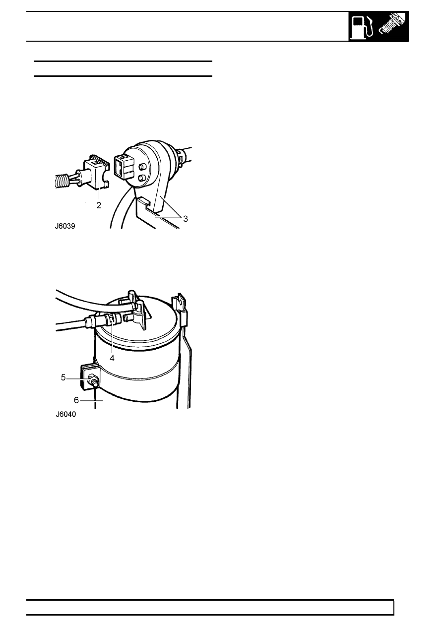
2. Disconnect multiplug from EVAP purge valve.
3. Release purge valve rubber mounting from

bracket.

4. Release clip and remove hose from EAVP

canister.

5. Loosen bolt.
6. Remove EVAP canister and purge valve

complete.

Refit

7. Reverse removal procedure.

17

EMISSION CONTROL

8

REPAIR

ADD: 09/95

EVAP CANISTER - ADVANCED EVAPS

Service repair no - 17.15.13

Remove

1. Disconnect battery negative lead.

2. Release clip securing vent solenoid hose to

canister and disconnect hose.

3. Release vent and purge line quickfit connections

from canister.

4. Remove nut and bolt securing canister to

mounting bracket, collect fixture clamp.

5. Remove canister.

Refit

6. Fit canister to mounting bracket.
7. Position fixture clamp and secure canister to

mounting bracket with nut and bolt.

8. Connect vent and purge line quickfit connections

to canister.

9. Connect vent solenoid hose to canister and

secure with clip.

10. Reconnect battery negative lead.

EVAP CANISTER PURGE VALVE - ADVANCED
EVAPS

Service repair no - 17.15.39

Remove

1. Disconnect battery negative lead.

2. Disconnect multiplug from purge valve.
3. Release purge valve rubber mounting from

bracket.

4. Release quickfit hose connections from throttle

body plenum and EVAP canister.

5. Remove purge valve assembly.

Refit

6. Locate purge valve adjacent to bracket.
7. Connect quickfit hose connections to throttle

body plenum and EVAP canister.

8. Conmnect multiplug to purge valve and secure

purge valve rubber mounting to bracket.

9. Reconnect battery negative lead.

EMISSION CONTROL

9

REPAIR

ADD: 09/95

EVAP CANISTER VENT SOLENOID - ADVANCED
EVAPS

Service repair no - 17.15.43

Remove

1. Disconnect battery negative lead.

2. Release clip securing hose to vent solenoid and

disconnect hose.

3. Disconnect multiplug from vent solenoid.
4. Remove vent solenoid from mounting bracket.

Refit

5. Fit vent solenoid to mounting bracket.
6. Connect multiplug to vent solenoid.
7. Connect hose to vent solenoid and secure with

clip.

8. Reconnect battery negative lead.

Tdi

1

DESCRIPTION AND OPERATION

DESCRIPTION

Air intake
The air cleaner is positioned to the right of the engine
and connected by hoses to a cold air intake duct and
the turbocharger inlet. A crankcase breather hose is
fitted between the air cleaner and the separator.

A single stage turbocharger, fitted between the
exhaust manifold and exhaust pipe, is connected by
hoses to the air cleaner and to an intercooler mounted
on the right of the radiator. The intercooler is
connected by a hose to the inlet manifold.

Fuel system
A 89 litre fuel tank is mounted at the rear of the
vehicle beneath the load space floor. The tank is
vented by a 2 way valve in the filler cap.

A mechanical lift pump, driven by the camshaft, is
mounted on the side of the engine.

A fuel filter, fitted with a replaceable element and
incorporating a water separator, is positioned on the
LH side of the bulkhead.

A Bosch Type injection pump, incorporating a cold
start advance unit and a high idle setting is mounted
on the LH side of the engine and is directly driven by
gears from the crankshaft. The pump meters and
distributes fuel to 4 pintle type injectors located in
pre-combustion chambers in the cylinder heads.

A return line passes excess fuel from the injection
pump and injectors back to the fuel tank.

Glow plugs
Four glow plugs are located in the cylinder head,
directly below each injector.

Exhaust gas recirculation (EGR)
Exhaust gas recirculation is controlled by the EGR
control unit mounted in the passenger compartment
on the RH ’A’ post behind the fascia and receives the
following inputs:

a. Engine temperature from coolant temperature

transmitter in No. 4 cylinder head.

b. Throttle position from the sensor on the injection

pump.

c. Engine speed from the tachometer.

d. EGR valve lift position.

When all correct signals are received, the EGR
solenoid allows vacuum to open the EGR valve and
recirculate a portion of the exhaust gas.


Content   ..  49  50  51  52   ..