Defender 300Tdi (1996+). Manual - part 106
86
ELECTRICAL
4
REPAIR
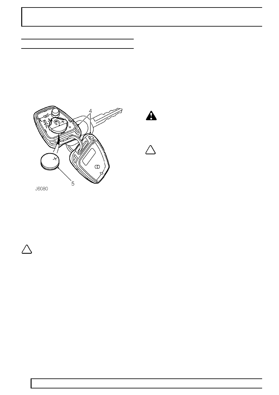
HANDSET BATTERY
Service repair no - 86.77.13
Remove
1. Unlock vehicle and disarm alarm system.
2. Turn starter switch to position ’II’.
3. Turn starter switch back to position ’0’ and
remove key.
4. Carefully prise handset apart, starting from
keyring end, using a coin or small screwdriver.
5. Slide battery out from retaining clip.
6. Press and hold one of the handset buttons for at
least five seconds to drain any residual power
from handset.
NOTE: The engine will immobilise five
minutes after key is removed from starter
switch.
Refit
7. Fit new battery into handset retaining clip with
positive side uppermost. Finger marks will
adversely affect battery life; if possible, avoid
touching flat surfaces of battery and wipe clean
before fitting.
8. Reassemble two halves of handset.
9. Press RH (Padlock) button at least four times
within range of vehicle to resynchronise handset.
10. Check operation of alarm system.
WARNING: The handset contains delicate
electronic circuits and must be protected
from impact and water damage, high
temperatures and humidity, direct sunlight and
effects of solvents, waxes and abrasive cleaners.
NOTE: New handsets must be be
initialised using TestBook.