Defender 300Tdi (1996+). Manual - part 72


  Index      Land Rover     Defender 300Tdi - service repair manual 1996 year


Search            


Content   ..  70  71  72  73   ..


Defender 300Tdi (1996+). Manual - part 72


70

BRAKES

12

REPAIR

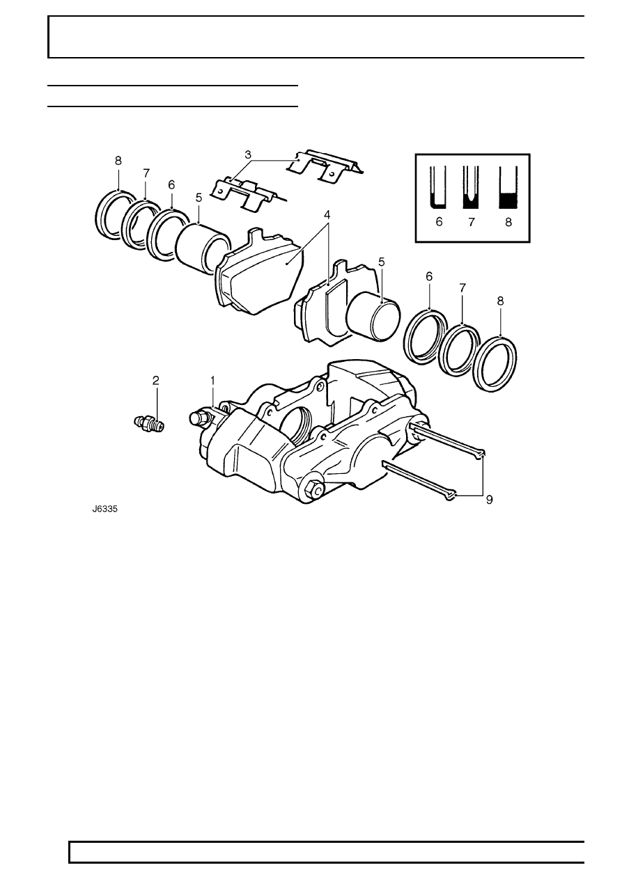
REAR BRAKE CALIPER ASSEMBLY

Key to rear caliper

1. Caliper
2. Bleed screw
3. Pad retaining springs
4. Brake pads
5. Piston

6. Wiper seal retainer
7. Wiper seal
8. Fluid seal
9. Retaining pins

BRAKES

13

REPAIR

REAR BRAKE CALIPERS

Service repair no - 70.55.06
Service repair no - 70.55.17

Before starting repair refer to General brake service
practice

See General Brake Service Practice.

Remove caliper

1. Remove rear road wheels.
2. Using a recognised hose clamp, clamp flexible

brake hose above rear axle.

90 Models

110/130 Models

3. Remove brake pipe from rear brake caliper.

4. Seal pipe ends to prevent ingress of dirt.
5. Remove retaining pins and springs and withdraw

pads. If same pads are to be refitted, identify
them for assembly in original positions.

6. Remove 2 bolts and withdraw caliper from rear

axle.

Repair

WARNING: Do not separate caliper halves.

7. Clean outer surfaces of caliper with aerosol

brake cleaner.

8. WITH CAUTION expel pistons from their bores

by applying air pressure to fluid inlet port. It is
unlikely both pistons will expel at same time,
regulate rate with a suitable piece of wood
inserted between two pistons.

9. Finally, remove pistons keeping them identified

with their respective bores.

10. Remove wiper seal retainer by inserting a blunt

screwdriver between retainer and seal and pry
retainer carefully from mouth of bore.

11. Taking care not to damage seal grooves, extract

wiper seal and fluid seal.

12. Clean bores, pistons and particularly seal

grooves using clean brake fluid only. If caliper or
pistons are corroded or their condition is not
perfect new parts must be fitted.

13. Apply brake fluid to new seal. Fit seal into

groove in bore. When seal is seated it feels
raised to touch at edge furthest away from
mouth of bore.

14. Coat piston with brake fluid. Insert it squarely

into bore. Do not tilt piston during insertion and
leave 8mm projecting from bore.

70

BRAKES

14

REPAIR

REV: 09/97

15. Coat a new wiper seal with brake fluid and fit to

new seal retainer. Slide assembly, seal first, over
protruding piston into bore recess.

16. Using special tool LRT-70-500 - piston clamp,

press home seal retainer and piston.

Mounting inboard piston

17. Carry out same procedure as for removing and

fitting outboard piston and seals, instructions 8 to
16.

Fit calipers and pads to vehicle

18. Fit caliper to axle, tighten 2 bolts evenly to

82

Nm (60 lbf/ft).

19. Connect brake pipe to caliper. Tighten to

15 Nm

(11 lbf/ft).

20. Remove clamp from flexible brake hose.

21. Insert pads and retaining springs, secure in

position with new retaining pins and spread ends
or fit new split pins, depending on vehicle model.
Note correct position of retaining springs on 90
models.

22. Bleed brake system

See Brake System Bleed .

23. Press brake pedal firmly several times to locate

pads.

24. Fit road wheels, remove axle stands. Finally

tighten road wheel nuts to correct torque:
Alloy wheels -

130 Nm (96 lbf/ft)

Steel wheels -

100 Nm (80 lbf/ft)

Heavy duty wheels -

170 Nm (125 lbf/ft)

25. Road test vehicle. Note new brake pads require

’bedding-in’, for several hundred miles before
brakes are at maximum efficiency.

REAR BRAKE DISC

Service repair no - 70.10.11.

Remove

1. Remove rear hub assembly

See REAR AXLE

AND FINAL DRIVE, Repair, Rear hub
assembly 
.

2. Remove disc bolts.
3. Remove disc from rear hub.

Refit

4. Fit disc to rear hub.
5. Fit disc bolts. Tighten to

73 Nm (54 lbf/ft).

6. Check total disc run out, this must not exceed

0,15 mm (0.006 in). If necessary reposition disc.

7. Fit rear hub assembly

See REAR AXLE AND

FINAL DRIVE, Repair, Rear Hub Assembly .

Disc reclamation

8. Check disc thickness. This dimension may be

machined to minimum thickness of 12 mm.
Machine equal amounts off each face.

NOTE: The brake disc MUST BE renewed if
the minimum running thickness stamped
on the disc is recorded.

BRAKES

15

REPAIR

TRANSMISSION BRAKE

1. Pin
2. Washer
3. ’C’ clip
4. Brake shoe
5. Cable lever
6. Hold down spring
7. Dished washer
8. Brake drum
9. Screw

10. Brake cable
11. Adjuster slide
12. Aadjuster nut

13. Spring
14. Adjuster slide
15. Adjuster bolt
16. Dished washer
17. Hold down spring
18. Brake shoe
19. Hold down pin
20. Hold down pin
21. Abutment plate
22. Back plate
23. Spring


Content   ..  70  71  72  73   ..