Defender 300Tdi (1996+). Manual - part 52


  Index      Land Rover     Defender 300Tdi - service repair manual 1996 year


Search            


Content   ..  50  51  52  53   ..


Defender 300Tdi (1996+). Manual - part 52


FRONT AXLE AND FINAL DRIVE

1

OVERHAUL

FRONT DIFFERENTIAL

Service repair no - 54.10.07.

Overhaul

NOTE: The front axle differential, for all
models, is the same as that fitted to the 90
rear axle and can only be serviced as a

complete assembly

See REAR AXLE AND FINAL

DRIVE, Repair, Differential assembly - 90 .

FRONT HUB

Service repair no - 60.25.14.

Overhaul

1. Remove hub assembly

See Repair, Front hub

assembly .

2. Remove outer bearing.
3. Mark, for reassembly, relationship between hub

and brake disc, if original hub is to be refitted.

4. Remove 5 bolts and separate hub from brake

disc.

5. Drift out grease seal and inner bearing from hub

and discard seal.

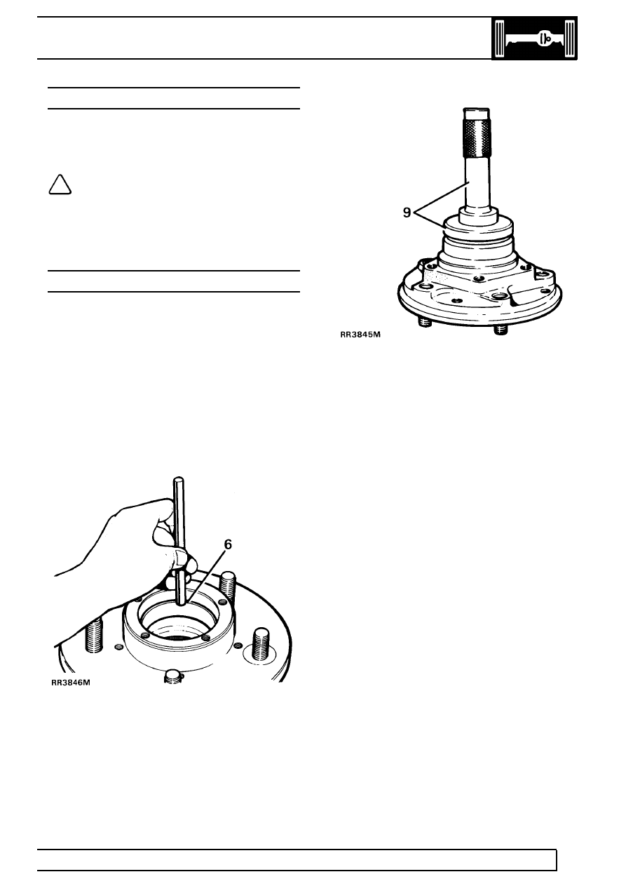
6. Drift out inner and outer bearing tracks.
7. Clean hub and drift in inner and outer bearing

tracks.

8. Pack hub inner bearing with recommended

grease and fit to hub.

9. With lip side leading fit new seal to hub using

special tool LST 137 seal replacer and drift 18G
134
. Drive in seal flush with rear face of hub.
Apply grease between seal lips.

10. Fit brake disc to hub, lining up to marks made

during dismantling. Applying Loctite 270, fit
retaining bolts. Tighten to

73 Nm (54 lbf/ft).

11. Grease and fit outer bearing to hub.
12. Fit hub assembly

See Repair, Front hub

assembly .

54

FRONT AXLE AND FINAL DRIVE

2

OVERHAUL

FRONT STUB AXLE, CONSTANT VELOCITY JOINT
AND SWIVEL PIN HOUSING

Service repair no - 60.15.43.

Remove stub axle, axle shaft and constant
velocity joint.

1. Remove front hub assembly

See Repair, Front

hub assembly .

2. Drain swivel pin housing and refit plug.

NOTE: On later vehicles the swivel pin
housing is filled with grease for life, the
level and drain plugs being deleted.

3. Remove 6 bolts retaining stub axle to swivel

housing.

4. Remove mud shield.
5. Remove stub axle and joint washer.

6. Wthdraw axle shaft and constant velocity joint

from axle casing.

Remove constant velocity joint from axle shaft

7. Hold axle shaft firmly in a soft jawed vice.
8. Using a soft mallet drive constant velocity joint

from shaft.

9. Remove circlip and collar from axle shaft.

Constant velocity joint

10. Mark positions of constant velocity joint, inner

and outer race and cage for reassembly.

11. Swivel cage and inner race to remove balls.

FRONT AXLE AND FINAL DRIVE

3

OVERHAUL

12. Examine all components, in particular, inner and

outer track, cage balls and bearing surfaces for
damage and excessive wear.

13. Maximum acceptable end-float on assembled

joint 0,64mm. Renew if worn or damaged.
Lubricate with a recommended oil during
assembly.

Fit constant velocity joint to axle

14. Fit collar and a new circlip.
15. Engage constant velocity joint on axle shaft

splines and using a soft mallet, drive joint in fully.

Renew stub axle, thrust ring, oil seal and bearing

16. Drill and chisel off thrust ring taking care to avoid

damaging stub axle.

17. Remove bearing and oil seal using special tool

TRT-37-004 and slide hammer LRT-99-004.
Ensure lip of tool locates behind bearing to to
drive it out.

18. Repeat instruction for removal of oil seal.

19. Lubricate seal and lip with EP90 oil and with

cavity side leading press in a new oil seal using
special tool LRT-54-004.

20. Using special tool LRT-54-005, fit bearing with

its part number visible when fitted, and flush with
end face of stub axle.

21. Press fit a new thrust ring onto stub axle.

54

FRONT AXLE AND FINAL DRIVE

4

OVERHAUL

Swivel pin housing

22. Remove bolts securing oil seal retaining plate

and joint washer. Release assembly from swivel
pin housing.

NOTE: Removal of oil seal and retaining
plate is achieved when swivel bearing
housing is removed.

23. Remove 2 bolts, retaining lower swivel pin to

housing.

24. Remove brake disc shield bracket.
25. Tap lug to remove lower swivel pin and joint

washer.

26. Remove two bolts retaining brake hose bracket

and top swivel pin.

27. Remove bracket, top swivel pin and shims.
28. Remove swivel pin housing while retrieving

lower and upper bearings.

Swivel bearing housing

29. Remove lower bearing track from swivel bearing

housing.

NOTE: Use upper bearing opening to gain
access to lower bearing track.

30. Remove 7 bolts retaining swivel bearing housing

to axle case.

31. Remove inner oil seal from back of housing.
32. Remove top bearing track from swivel bearing

housing.

NOTE: Use lower bearing opening to gain
access to upper bearing track.

33. If worn, pitted or damaged, renew housing.
34. Fit upper and lower bearing tracks into swivel

bearing housing.

CAUTION: Ensure bearing tracks are fitted
square or damage could occur.

35. With seal lips trailing, fit swivel housing inner oil

seal into rear of housing. Grease seal lips.

Fit swivel pin housing

36. Coat swivel bearing housing to axle casing bolts

with Loctite 270 or equivalent.

37. Coat both sides of joint washer with a sealing

compound. Position swivel bearing housing to
axle mating face.

Swivel assembly components

1. Swivel pin housing
2. Top swivel pin and brake hose bracket
3. Upper and lower swivel pin bearings
4. Shim
5. Retaining plate and washer
6. Oil seal
7. Joint washer
8. Swivel bearing housing
9. Joint washer

10. Lower swivel pin
11. Mudshield bracket
12. Swivel housing inner oil seal


Content   ..  50  51  52  53   ..