Defender 300Tdi (1996+). Manual - part 33


  Index      Land Rover     Defender 300Tdi - service repair manual 1996 year


Search            


Content   ..  31  32  33  34   ..


Defender 300Tdi (1996+). Manual - part 33


30

MANIFOLD AND EXHAUST SYSTEM

2

DESCRIPTION AND OPERATION

The catalyst comprises platinum coated ceramic
elements. The Hydrocarbons (HC), Oxides of nitrogen
(NOx) and Carbon monoxide (CO) emitted by the
engine react with the catalytic element and exhaust
temperature to convert the toxic gas into Nitrogen
(N

2

), Carbon dioxide (CO

2

) and water vapour.

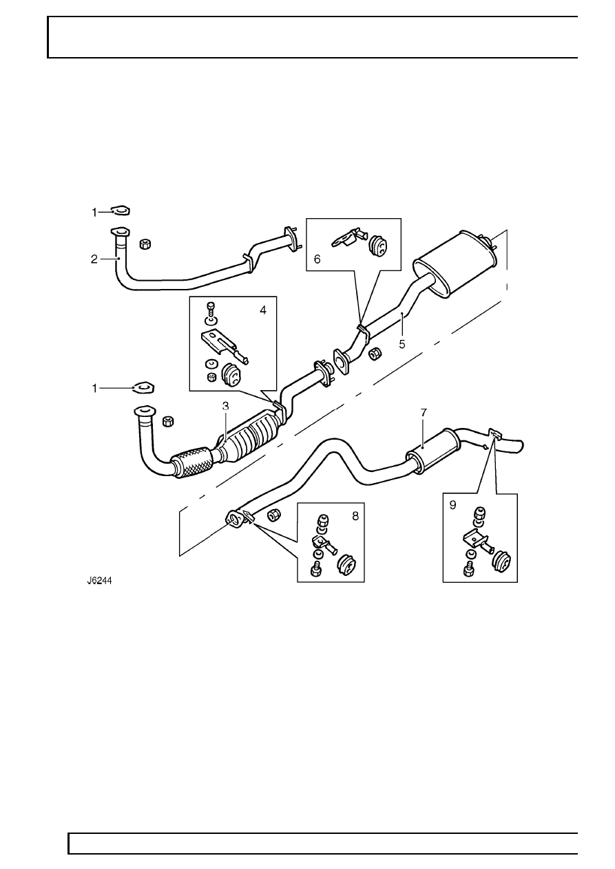
Exhaust system - 110/130

1. Gasket
2. Front pipe
3. Front pipe with catalytic converter
4. Front mounting bracket
5. Intermediate silencer

6. Intermediate mounting brackets
7. Tail pipe silencer
8. Tail pipe silencer mounting
9. Tail pipe mounting

MANIFOLD AND EXHAUST SYSTEM

1

REPAIR

INDUCTION MANIFOLD

Service repair no - 30.15.02

Remove

1. Disconnect battery.
2. Remove oil filler cap and remove rocker cover

insulation.

3. Remove hose intercooler to induction manifold. If

fitted, remove EGR valve.

See FUEL SYSTEM,

Repair, EGR valve

4. Remove 2 screws and release heat shield from

induction manifold.

5. Slacken induction manifold lower securing nuts,

located below exhaust manifold.

6. Remove induction manifold upper securing bolts.
7. Remove induction manifold. Plug apertures in

cylinder head with clean rag to prevent any items
falling into engine.

8. Check gasket is satisfactory for further use.

Refit

9. Clean induction manifold mating face.

10. Position induction manifold and secure with

upper and lower fixings.

11. Tighten securing nuts and bolts to

25 Nm (18

lbf/ft).

12. Fit manifold heat shield.
13. Fit hose intercooler to induction manifold.
14. Fit rocker cover insulation.
15. Reconnect battery.

INDUCTION/EXHAUST MANIFOLD GASKET

Service repair no - 30.15.15

Remove

1. Remove induction manifold

See Induction

manifold .

2. Remove turbocharger outlet hose.
3. Raise vehicle and slacken exhaust front pipe to

intermediate silencer flange nuts. Ensure pipe is
free to turn.

NOTE: If removing exhaust manifold and
turbocharger assembly from vehicle,
remove manifold to exhaust front pipe

nuts while working under vehicle.

4. Remove exhaust manifold securing nuts,

removing centre lower nut first.

5. Move heater rail clear of exhaust manifold.
6. With exhaust manifold and turbocharger still

attached to exhaust front pipe, withdraw from
head by turning front pipe until sufficient access
is gained to remove gasket.

7. Suitably support exhaust manifold and

turbocharger assembly to prevent damage.

8. Remove induction manifold lower nuts.
9. Remove gasket.

10. Clean mating faces.

30

MANIFOLD AND EXHAUST SYSTEM

2

REPAIR

Refit

11. Fit new gasket over manifold studs.
12. Loosely fit induction manifold lower nuts to

studs.

13. Fit exhaust manifold and secure with central

upper and lower nuts.

14. Locate heater rail to its correct position and

secure with outer exhaust manifold nuts.

15. Tighten all exhaust manifold nuts to

45 Nm (33

lbf/ft).

16. Tighten exhaust front pipe to intermediate

silencer nuts to

50 Nm (37 lbf/ft).

17. Fit turbocharger outlet pipe.
18. Fit induction manifold

See Induction manifold

.

EXHAUST MANIFOLD/TURBOCHARGER
ASSEMBLY

Service repair no - 30.15.10

Remove

1. Remove induction manifold

See Induction

manifold .

2. Disconnect turbocharger inlet hose.
3. Disconnect boost pressure pipe at turbocharger.

4. Remove intercooler bottom hose.
5. Place suitable container under engine and

disconnect turbocharger oil feed and return
pipes at cylinder block.

6. Remove 3 nuts securing exhaust front pipe to

manifold flange.

7. Remove 7 nuts and lift exhaust manifold and

turbocharger assembly from cylinder head.

8. Discard manifold gasket.

Refit

9. Fit new manifold gasket.

10. Position exhaust manifold assembly onto

location studs and secure to cylinder head.
Tighten nuts to

45 Nm (33 lbf/ft).

11. Secure exhaust front pipe to manifold flange.

Tighten fixings to

50 Nm (37 lbf/ft).

12. Reconnect turbocharger oil feed and return

pipes at cylinder block.

13. Fit intercooler bottom hose.
14. Fit boost pressure pipe at turbocharger.
15. Fit turbocharger inlet hose.
16. Fit induction manifold

See Induction manifold

.

MANIFOLD AND EXHAUST SYSTEM

3

REPAIR

EXHAUST FRONT PIPE

Service repair no - 30.10.09

Remove

1. Disconnect battery.
2. Raise vehicle on ramp.

3. Remove 3 securing nuts at exhaust manifold

flange.

4. Remove through bolt securing front pipe

mounting bracket to chassis.

5. Remove bracket and rubber mounting from

exhaust pipe.

NOTE: A chassis undertray may be fitted
on some vehicle derivatives to conform to
legal requirements. When under chassis

remove and refit procedures are required, it may
be necessary to remove the undertray

See

CHASSIS AND BODY, Repair, Front undertray or
See CHASSIS AND BODY, Repair, Rear undertray
.

6. Remove flange nuts securing front pipe to

intermediate silencer assembly and separate
flanges.

7. Release front pipe at manifold and remove

gasket.

8. Move front pipe rearwards, lower front end and

at the same time twist toward propeller shaft.
Move pipe forward and withdraw from under
vehicle.

Refit

9. Manouvre front pipe into position and secure to

intermediate silencer flange. Do not fully tighten
fixings at this stage.

10. Fit new gasket and secure front pipe to exhaust

manifold. Tighten fixings to

50 Nm (37 lbf/ft).

11. Fit front pipe bracket and mounting rubber to

chassis.

12. Fully tighten front pipe to intermediate silencer

flange nuts to

30 Nm (22 lbf/ft).

13. Lower vehicle ramp and reconnect battery.


Content   ..  31  32  33  34   ..