Defender 300Tdi (1996+). Manual - part 32


  Index      Land Rover     Defender 300Tdi - service repair manual 1996 year


Search            


Content   ..  30  31  32  33   ..


Defender 300Tdi (1996+). Manual - part 32


COOLING SYSTEM

5

REPAIR

28. Secure steering pump and bracket to auxiliary

mounting bracket.

29. Fit steering pump pulley.
30. Fit drive belt

See ELECTRICAL, Repair,

Auxiliary drive belt .

31. Fit fan cowl

See Fan cowl .

32. Fit viscous fan unit

See Viscous coupling and

fan .

33. Fit intercooler top hose.
34. Fit radiator top hose.
35. Refill cooling system.

See Adjustment, Drain

and refill cooling system

36. Reconnect battery.

THERMOSTAT

Service repair no - 26.45.01
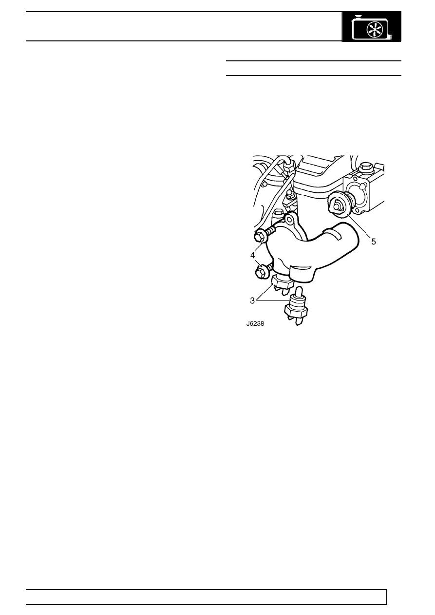
Remove

1. Partially drain cooling system, until coolant level

is below thermostat housing.

2. Disconnect top hose from outlet elbow.

3. Disconnect electrical connections to water

temperature switch.

4. Unscrew 2 bolts and remove outlet elbow.
5. Withdraw thermostat. Note 88

°

C rating of

thermostat.

6. Place thermostat in a container half full of water.

Heat water and observe temperature at which
thermostat begins to open. Thermostat is
satisfactory if it opens between 85

°

- 89

°

C.

Refit

7. Fit thermostat with jiggle pin/vent hole upwards.
8. Secure outlet elbow to thermostat housing.

Tighten bolts to

25 Nm (18 lbf/ft).

9. Fit water temperature switch connections.

10. Fit top hose to outlet elbow.
11. Refill cooling system.

See Adjustment, Drain

and refill cooling system

26

COOLING SYSTEM

6

REPAIR

RADIATOR

Service repair no - 26.40.01

Remove

1. Disconnect radiator bottom hose and drain

cooling system.

See Adjustment, Drain and

refill cooling system

2. Disconnect radiator top hose.
3. Remove viscous fan unit.

See Viscous

coupling and fan

4. Remove fan cowl.

See Fan cowl

5. Disconnect oil cooler pipes. Plug all connections

to prevent oil spillage and ingress of dirt.

6. Disconnect top and bottom intercooler hoses.
7. Disconnect bleed hose at radiator.
8. Remove 2 bolts from both sides securing

radiator mounting brackets to bonnet platform.

9. Lift and remove radiator/intercooler assembly

from vehicle.

10. Remove 2 bolts from both sides and detach

radiator top cover from side covers.

11. Lift and remove radiator from intercooler and RH

side frame.

12. Check condition of locating grommets in radiator

top cover and lower mounting bushes. Renew if
necessary.

Refit

13. Position radiator between intercooler and RH

side frame.

14. Fit radiator top cover to side covers.
15. Lower radiator/intercooler assembly into

position.

16. Secure radiator mounting brackets to bonnet

platform.

17. Fit radiator bleed hose.
18. Fit top and bottom intercooler hoses.
19. Fit oil cooler pipes.
20. Fit fan cowl

See Fan cowl .

21. Fit viscous fan unit.

See Viscous coupling

and fan

22. Fit radiator top hose.
23. Fit radiator bottom hose and refill cooling

system.

See Adjustment, Drain and refill

cooling system

COOLING SYSTEM

7

REPAIR

EXPANSION TANK

Service repair no - 26.15.01

Remove

1. Position container to collect coolant spillage.

2. Slacken retaining clips and disconnect both

hoses from base of expansion tank.

3. Remove 3 bolts securing expansion tank to

inside wing and mounting bracket.

4. Remove expansion tank.

Refit

5. Fit expansion tank to inside wing and mounting

bracket.

6. Fit both hoses to base of tank.
7. Check and top up cooling system

See

SECTION 10, Maintenance, Under bonnet
maintenance

MANIFOLD AND EXHAUST SYSTEM

1

DESCRIPTION AND OPERATION

MANIFOLDS AND EXHAUST SYSTEM

Description

The exhaust systems fitted on all models with the
300Tdi engine comprise three sections; front pipe
assembly, intermediate silencer assembly, and tail
pipe and silencer assembly. All sections, including
silencers, are manufactured from luminised steel to
give the system a durable working life under all
conditions. Special clamps are provided to ensure

leak proof jointing between the various sections,
which are supported by flexible rubber mountings.

Catalytic convertor

When fitted, the catalytic converter is integral with the
front pipe assembly, which also incorporates a flexible
joint. The catalyst forms part of the engine emission
control that can also include an EGR valve system
See FUEL SYSTEM, Repair, EGR valve

Exhaust system - 90

1. Gasket
2. Front pipe
3. Front pipe with catalytic converter
4. Front mounting bracket
5. Intermediate silencer

6. Intermediate mounting brackets
7. Tail pipe silencer*
8. Tail pipe silencer mounting
9. Tail pipe mounting

* Deleted on later models


Content   ..  30  31  32  33   ..