Defender 90 NAS. Manual - part 77


  Index      Land Rover     Defender 90 NAS - service manual 1997 year


Search            


Content   ..  75  76  77  78   ..


Defender 90 NAS. Manual - part 77


76

CHASSIS AND BODY

6

REPAIR

Refit

6. Feed control rod into position and loosely secure

lever to mounting panel with 2 screws.

7. Connect control rod to latch mechanism and

secure with spring clip.

8. Tighten control lever retaining screws.
9. Secure control rod to plastic clip in mounting

panel.

10. Secure plastic sheet with adhesive.
11. Fit door trim casing.

See Trim casing - front

door

EXTERIOR HANDLE - FRONT DOOR

Service repair no - 76.58.01

Remove

1. Remove door trim casing.

See Trim casing -

front door

2. Remove mounting panel.
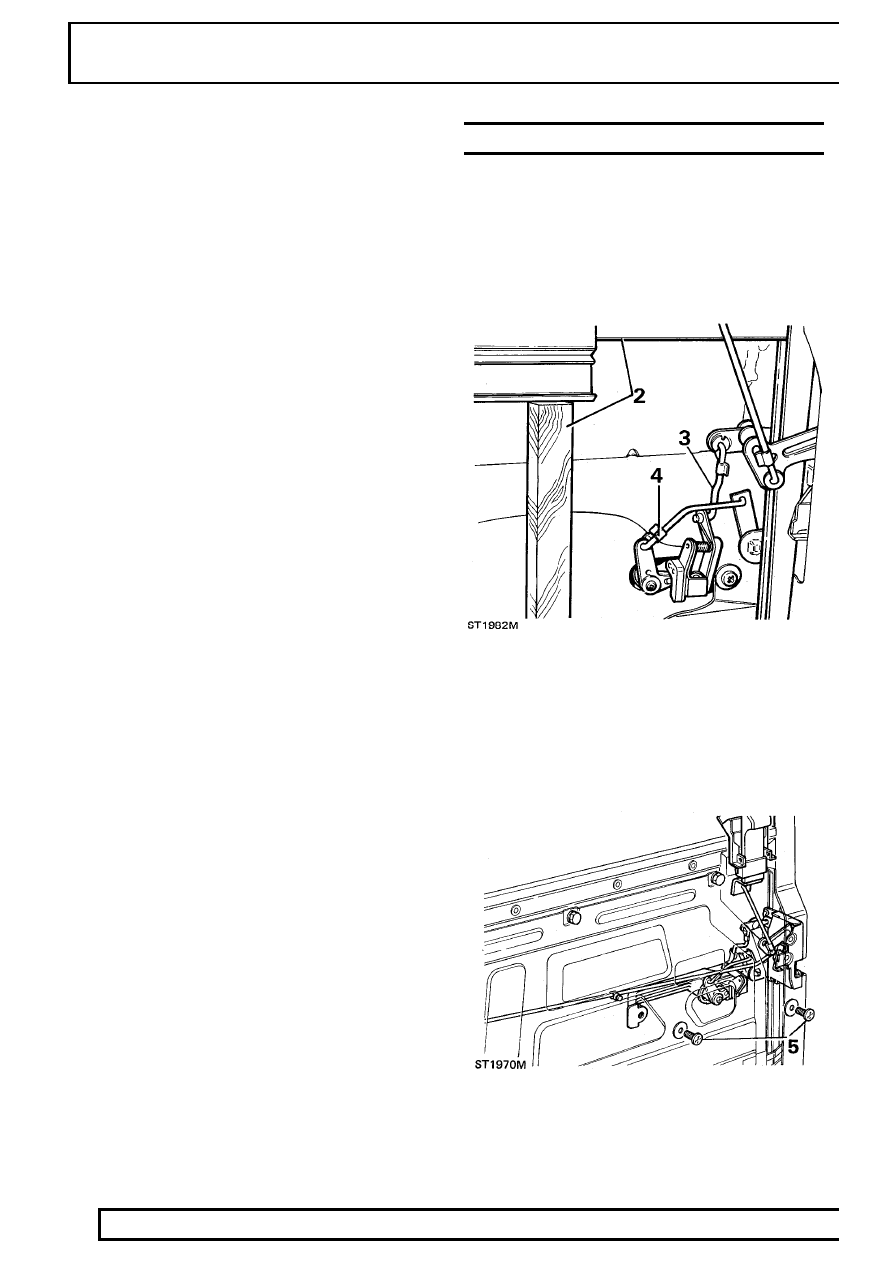
See Mounting panel

- front door and support glass with timber.

3. Disconnect operating rod from handle

mechanism.

4. Disconnect rod from locking barrel lever.

5. Remove 2 screws and withdraw handle

assembly.

CHASSIS AND BODY

7

REPAIR

Refit

6. Fit handle to door ensuring that two bezels are in

position - flat faces towards door, and secure
with 2 screws.

7. Connect rod to handle operating lever and

secure with spring clip.

8. Connect rod to locking barrel lever and retain

with spring clip.

9. Fit mounting panel

See Mounting panel - front

door

10. Fit door trim casing.

See Trim casing - front

door

76

CHASSIS AND BODY

8

REPAIR

LATCH ASSEMBLY - FRONT DOOR

Service repair no - 76.37.12

Remove

1. Remove mounting panel.

See Mounting panel

- front door and support glass with timber.

2. Disconnect control rod from handle operating

lever.

3. Disconnect control rod from locking lever on

handle.

4. Disconnect locking button control rod from latch

mechanism.

5. Remove 2 screws and remove handle assembly

from door.

6. Remove 2 self-tapping screws retaining lower

end of window glass runner.

7. Remove 3 screws securing latch assembly to

door.

8. Whilst taking care not to damage runner, ease

runner away from latch and manoeuvre latch
asembly from door.

Refit

9. Carefully ease window runner away, sufficiently

to enable latch to be located into position.

10. Secure latch to door with 3 screws.
11. Secure window runner with 2 screws ensuring

that packing strip is in position and that screw
heads are below bottom of runner to prevent
damage to glass.

12. Fit handle with 2 screws, ensuring that bezels

are in position.

13. Connect control rod to handle operating lever

and secure with spring clip.

14. Connect control rod to locking lever and retain

with spring clip.

15. Connect locking button control rod to latch lever

and secure with spring clip.

16. Fit mounting panel.

See Mounting panel -

front door

CHASSIS AND BODY

9

REPAIR

DOOR GLASS - FRONT DOOR

Service repair no - 76.31.01

Remove

1. Remove mounting panel.

See Mounting panel

- front door

2. Remove window regulator.

See Window

regulator - front door

3. Push glass up to top of its travel and support

with a suitable length of timber.

4. Remove 2 self tapping screws securing window

glass runner on latch side of door and single
screw from hinge side.

5. Taking care not to damage paint, prise exterior

waist weather strip from door.

6. Remove timber support and lower glass to

bottom of door.

7. Ease runner from glass at hinge side of door, lift

glass over bottom edge of door and withdraw.


Content   ..  75  76  77  78   ..