Defender 90 NAS. Manual - part 62


  Index      Land Rover     Defender 90 NAS - service manual 1997 year


Search            


Content   ..  60  61  62  63   ..


Defender 90 NAS. Manual - part 62


57

STEERING

10

OVERHAUL

Adjustments

91. Note where greatest figures are recorded

relative to steering position. If greatest figures
are not recorded across centre of travel (steering
straight-ahead), adjust as follows:

If torque peak occurs before centre position, add to
shim washer value; if torque peak occurs after centre
position, subtract from shim washer value,

refer to

fitting valve and worm assembly .

Shim washers are available as follows:
0.03mm, 0.07mm, 0.12mm and 0.24mm
0.001in, 0.003in, 0.004in and 0.008in.

NOTE: Adjustment of 0.07mm, 0.003 in to
shim value will move torque peak area by
1/4 turn on the shaft.

CAUTION: When reshimming valve and
worm, extreme caution must be exercised
to prevent seal damage during

reassembly.

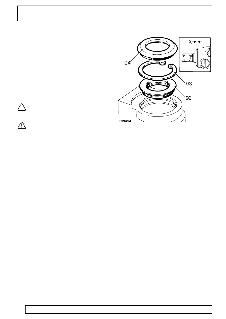
Input shaft oil seal

92. Fit seal, lip side first, into housing. Use seal

saver LRT-57-016and seal installer LRT-57-026.
Note that seal is fitted to a depth of 4.75 - 5.00
mm, 0.19 - 0.20 in from face of box.

93. Secure seal with circlip.
94. Smear inner lip of dirt excluder with grease. Fit

dirt excluder using LRT-57-027. When fitted
correctly outer shoulder of excluder is 4.00 - 4.50
mm, 0.16 - 0.18 in from face of box, dimension
’X’.

95. Remove drop arm. Smear inner lip of dirt

excluder with PTFE grease and refit, ensuring
outer lip is flush with casing.

96. With input shaft on centre, align assembly marks

on drop arm and steering box. Fit drop arm to
steering box using a new tab washer. Tighten
nut to

175 Nm, 130 lbf ft, bend over tab.

97. Fit steering box

See Repair, Power Steering

Box .

STEERING

1

SPECIFICATIONS, TORQUE

TORQUE VALUES

Nm

lbf ft

Drag link to drop arm

40

........................................................

30

Ball joint nuts

40

....................................................................

30

Clamp bolt nuts

14

................................................................

10

Steering column bracket nuts

22

...........................................

16

Steering wheel nut

50

...........................................................

37

Tie bar to mounting nut

110

....................................................

80

Universal joint pinch bolt

25

..................................................

18

PAS box

Adjuster locknut

60

.......................................................

45

Drop arm nut

175

...........................................................

130

Sector shaft cover to steering box

75

...........................

55

Steering box to chassis

80

...........................................

60

Steering box fluid pipes 14mm thread

15

.....................

11

Steering box fluid pipes 16mm thread

20

.....................

15

Tie bar

80

.....................................................................

60

Adjuster grub screw

5

................................................

4

PAS pump

High pressure fluid pipe

20

..........................................

15

Power steering pump mounting

35

..............................

25

Pulley bolts, power steering pump

10

..........................

7

Hose clamp

3

.............................................................

2

Front clamping bracket bolts

9

...................................

7 PAS reservoir

Hose clamp

3

.............................................................

2

The following Torque values are for screws and bolts that are not specified on previous page.

METRIC

Nm

lbf ft

M5

6

...........................................................................

4.5

M6

9

...........................................................................

7

M8

25

...........................................................................

18

M10

45

.........................................................................

33

M12

90

.........................................................................

65

M14

105

.........................................................................

77

M16

180

.........................................................................

133

UNC / UNF

1/4

9

...........................................................................

7

5/16

24

.........................................................................

18

3/8

39

...........................................................................

29

7/16

78

.........................................................................

58

1/2

90

...........................................................................

65

5/8

135

...........................................................................

100

FRONT SUSPENSION

1

DESCRIPTION AND OPERATION

DESCRIPTION

The front suspension design allows maximum wheel
travel and axle articulation providing good ground
clearance without loss of traction or directional
stability. A wheel speed sensor is attached to each
swivel housing with a reluctor ring on the constant
velocity joints. The input from the wheel sensors are
used by the engine management ECM for ’Off-road
detection’.

Long radius arms are fitted to the front axle and
provide maximum axle articulation which is vital for off
road performance. The radius arms are secured to
fabricated mounting brackets welded to the front axle.
Flexible rubber bushes are used on a stem end joint
to secure the rear of the radius arms to mountings on
the chassis cross member.

A panhard rod, which ensures that the front axle
remains centrally located, is fitted transversely and

also uses ferrule rubber bush mountings at both axle
and chassis locations.

Two rubber bearing bushes, with retaining straps,
secure the rear of the anti-roll bar to the chassis
mountings, while bushed links support the front of the
bar to the front axle.

Conventional long travel coil springs and hydraulic
shock absorbers are used to control body movement
in all conditions. The shock absorbers are secured to
fabricated towers which are bolted to the chassis. The
upper and lower fixings use a single location stud with
flexible rubber bushes, support washers and securing
nuts. Retaining plates are used to secure the coil
springs to the fabricated towers and axle mountings.

Rubber bump stops are fitted underneath the chassis,
adjacent to the front road springs, and prevent
possible damage that could occur should there be
excessive axle to chassis movement.

Front suspension

1. Panhard rod
2. Radius arms
3. Coil springs

4. Shock absorber
5. Anti-roll [sway] bar

FRONT SUSPENSION

1

REPAIR

SELF LOCKING NUTS

WARNING: Where self locking nuts are
removed, they must be replaced with new
nuts of same specification.

ANTI-ROLL [SWAY] BAR

Service repair no - 60.10.01

Remove

1. Raise vehicle on a ramp [hoist].

2. Mark anti-roll [sway] bar rubber bushes for

reassembly.

3. Remove 4 nuts and bolts securing anti-roll

[sway] bar to mounting brackets.

4. Remove 2 nuts and bolts securing anti-roll

[sway] bar to ball joint links.

5. Remove anti-roll [sway] bar.
6. Remove rubber bushes from anti-roll [sway] bar.

Refit

7. Fit bushes to anti-roll [sway] bar. Ensure split in

bushes points towards axle on RH side, and
away from axle on LH side.

8. Position anti-roll [sway] bar and loosely fit nuts

and bolts to mounting brackets.

NOTE: Angled sides of bar should point
downwards.

9. Using new nuts, fit anti-roll [sway] bar to ball joint

links. Tighten to

68 Nm, 50 lbf ft.

10. Tighten nuts and bolts securing anti-roll [sway]

bar to mounting brackets to

30 Nm, 22 lbf ft.

11. Lower vehicle.


Content   ..  60  61  62  63   ..