Defender 90 NAS. Manual - part 50


  Index      Land Rover     Defender 90 NAS - service manual 1997 year


Search            


Content   ..  48  49  50  51   ..


Defender 90 NAS. Manual - part 50


54

FRONT AXLE AND FINAL DRIVE

2

OVERHAUL

FRONT STUB AXLE, CONSTANT VELOCITY JOINT
AND SWIVEL PIN HOUSING

Service repair no - 60.15.43.

Remove stub axle, axle shaft and constant
velocity joint.

1. Remove front hub assembly.

See Repair,

Front Hub Assembly

2. Drain swivel pin housing and refit plug.

NOTE: On later vehicles the swivel pin
housing is filled with grease for life
service. The level and drain plugs have

been deleted.

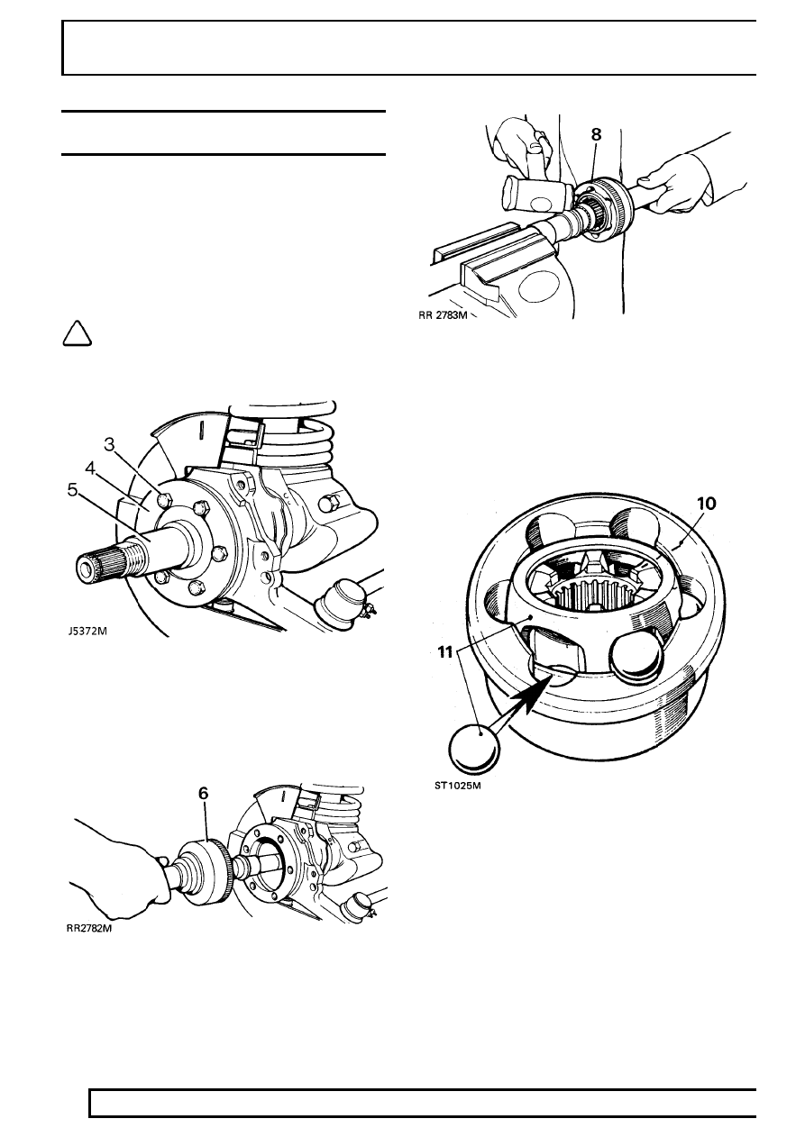
3. Remove 6 bolts retaining stub axle to swivel

housing.

4. Remove mud shield.
5. Remove stub axle and joint washer.

6. Pull out axle shaft and constant velocity joint

from axle casing.

Remove constant velocity joint from axle shaft

7. Hold axle shaft firmly in a soft jawed vice.
8. Using a soft mallet drive constant velocity joint

from shaft.

9. Remove circlip and collar from axle shaft.

Constant velocity joint

10. Mark positions of constant velocity joint, inner

and outer race and cage for reassembly.

11. Swivel cage and inner race to remove balls.

FRONT AXLE AND FINAL DRIVE

3

OVERHAUL

12. Examine all components in particular inner and

outer track, cage balls and bearing surfaces for
damage and excessive wear.

13. Maximum acceptable end-float on assembled

joint 0,64mm, 0.025 in. Renew if worn or
damaged. Lubricate with a recommended oil
during assembly.

Fit constant velocity joint to axle

14. Fit collar and a new circlip.
15. Engage constant velocity joint on axle shaft

splines and using a soft mallet, drive joint in fully.

Renew stub axle,thrust ring, oil seal and bearing

16. Drill and chisel off thrust ring taking care to avoid

damaging stub axle.

17. Remove bearing and oil seal using special tool

LRT-37-004and slide hammer LRT-99-004.
Ensure lip of tool locates behind bearing to to
drive it out.

18. Repeat instruction for removal of oil seal.

19. Lubricate seal and lip with EP90 oil and with

cavity side leading press in a new oil seal using
special tool LRT-54-004.

20. Using special tool LRT-54-005, fit bearing with

its part number visible when fitted, and flush with
end face of stub axle.

21. Press fit a new thrust ring onto stub axle.

54

FRONT AXLE AND FINAL DRIVE

4

OVERHAUL

Swivel pin housing assembly

22. Remove brake disc shield bracket.
23. Disconnect track-rod end ball joint from housing.
24. Disconnect drag-link ball joint.
25. Disconnect jump hoses from brake jump hose

bracket.

26. Remove road speed sensor.
27. Remove 6 bolts securing oil seal and retaining

plate to swivel pin housing. Prise seal from
swivel pin housing.

NOTE: Oil seal and retaining plate cannot
be removed until swivel pin bearing
housing is removed.

28. Remove 2 screws securing brake damper/shield

bracket, and lower swivel pin to housing.

29. Withdraw lower swivel pin and joint washer by

tapping protruding lug.

30. Remove top swivel pin retaining bolts complete

with brake jump hose bracket.

31. Remove top swivel pin and shims.
32. Remove swivel pin housing while retrieving

lower taper bearing.

Swivel pin bearing housing

33. Remove 7 bolts securing swivel pin bearing

housing to axle case.

34. Remove and discard oil seal and joint washer.
35. Remove lower swivel pin bearing track.
36. Remove top swivel pin bush housing assembly.

Discard two thrust washers and bearing.

37. If worn, pitted or damaged, renew swivel pin

bearing housing.

38. Fit a new lower swivel pin bearing track.
39. Fit a new bush and bush housing. Ensure

relieved lip of bush housing faces towards rear,
as shown.

40. With seal lips trailing press axle shaft oil seal

flush into rear of housing. Grease lips.

41. Fit new thrust washers and bearing into top

swivel pin bush.

42. Hang swivel pin bearing housing oil seal and

retainer plate over back of housing. Ensure they
are in correct assembly order.

43. Fit a new joint washer and secure swivel pin

bearing housing to axle. Starting with top fixing
dowel bolt. Tighten to

72Nm, 52 lbf ft.

Fit swivel pin housing

44. Grease and fit lower swivel pin bearing to

bearing housing.

45. Place swivel pin housing in position over swivel

pin bearing housing.

46. Using a new joint washer, fit lower swivel pin

with lip outboard. Do not secure with screws at
this stage.

47. Fit a new sensor bush and new oil seal, lip side

leading to top swivel pin.

48. Lubricate with a recommended oil and fit top

swivel pin with existing shims.

49. Coat threads of top swivel pin bolts with Loctite

542. Fit bolts and jump hose bracket (do not
tighten).

50. Coat threads of lower swivel pin screws with

Loctite 270 and fit, together with damper and
shield bracket. Tighten to

25 Nm, 18 lbf ft.

51. Tighten top swivel pin and brake jump hose

bracket securing bolts to

65 Nm, 50 lbf ft.

Check and adjust preload on bearings

52. The preload on bearings to be 0,25 to 0,30 mm,

0.010 to 0.012 in without swivel housing oil seal
and axle fitted, and reading from centre of swivel
pin. The torque required to turn swivel assembly
from lock to lock to be

2.0 to 2.8 Nm, 1.5 to 2.0

lbf ft. Adjust by removing or adding shims as
necessary.

53. To take a reading use special tool

LRT-57-024torque test adaptor, with a torque
wrench and extension as shown.

FRONT AXLE AND FINAL DRIVE

5

OVERHAUL

54. Apply a recommended grease between lips of

swivel housing oil seal.

55. Secure oil seal with retaining plate and securing

bolts. Tighten to

11Nm, 8 lbf ft.

56. Fit track-rod and drag link and secure with new

cotter pins.

57. Loosely fit lock stop bolt for later adjustment.
58. Fit brake disc shield.

Fit driveshaft and stub axle

59. Insert axle shaft, and when differential splines

are engaged, push assembly in fully.

CAUTION: Take care not to damage axle
shaft oil seals.

60. Place a new joint washer in position on swivelpin

housing to stub axle mating face. Coat threads
of stub axle bolts with Loctite 270.

61. Fit stub axle with flat at 12 O’clock position.

CAUTION: Ensure that constant velocity
joint bearing journal is butted against
thrust ring on stub axle before stub axle is

secured.

62. Place mud shield in position and secure stub

axle to swivel pin housing with six bolts and
tighten evenly to

65 Nm, 48 lbf ft.

63. Fit brake jump hoses to brake jump hose

bracket.

64. Fit front hub complete assembly.

See Repair,

Front Hub Assembly

65. Fill swivel assembly with correct amount of

lubricant.

See SECTION 10, Maintenance,

Under vehicle maintenance .

NOTE: Vehicles with a filler plug only must
be filled with 0.33 Litres, 0.75 pt of Molytex
EP 00 grease.

66. Set steering lock stop bolts.

See STEERING,

Adjustment, Steering Lock Stops

67. Fit Wheel speed sensor.

See FUEL SYSTEM,

Repair, Wheel speed sensor - Front


Content   ..  48  49  50  51   ..