Defender 90 NAS. Manual - part 41


  Index      Land Rover     Defender 90 NAS - service manual 1997 year


Search            


Content   ..  39  40  41  42   ..


Defender 90 NAS. Manual - part 41


44

AUTOMATIC GEARBOX

2

REPAIR

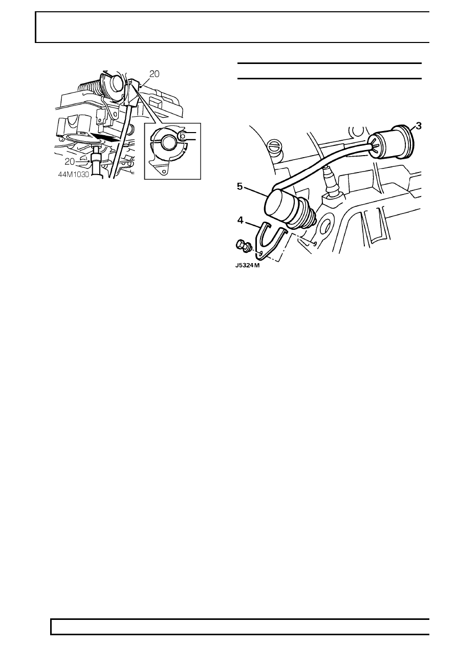
20. Locate selector linkage setting gauge

LRT-44-002in position and gently press control
unit forwards as shown. Tighten bolts to

8 Nm, 6

lbf ft.

21. Remove setting gauge.
22. Refit gearbox fluid pan

See Fluid pan gasket

and screen.

23. Lower vehicle on ramp [hoist].
24. Adjust kickdown cable

See Adjustment,

Kickdown cable adjustment.

25. Reconnect battery negative lead.
26. Refill gearbox oil using correct grade of oil

See

LUBRICANTS, FLUIDS AND CAPACITIES,
Information, Recommended Lubricants and
Fluids.

INHIBITOR SWITCH

Service repair no - 44.15.19

Remove

1. Site vehicle on a four post ramp [hoist].
2. Disconnect battery negative lead. Raise vehicle.
3. Disconnect inhibitor switch multiplug.
4. Remove inhibitor switch retaining plate.
5. Remove inhibitor switch.
6. Remove ’O’ ring seal.
7. Clean inhibitor switch.

Refit

8. Clean mating face on casing.
9. Fit and lubricate NEW ’O’ ring seal to switch.

10. Fit switch to casing.
11. Secure with retaining plate and bolt.
12. Connect multiplug to harness.
13. Reconnect battery and remove vehicle from

ramp [hoist].

AUTOMATIC GEARBOX

3

REPAIR

FLUID PAN GASKET AND SCREEN

Service repair no - 44.24.05 - Fluid pan gasket
Service repair no - 44.24.07 - Fluid screen

Remove

1. Site vehicle on a four post ramp [hoist].
2. Disconnect battery negative lead.
3. Raise vehicle.
4. Drain fluid and refit plug with new seal. Tighten

to

43 Nm, 32 lbf ft.

5. Remove catalytic converter assembly

See

EMISSION CONTROL, Repair, Front
pipe/catalytic converter.

6. Release fuel pipes from retaining clip secured by

top RH chassis crossmember bolt.

7. Remove 8 bolts securing chassis crossmember.
8. With assistance and using a body jack between

chassis longitudinals, jack chassis sufficiently to
enable removal of crossmember.

9. Disconnect dipstick tube from fluid pan. Loosen

securing bolt at bell housing and move tube
aside.

10. Remove clamps securing fluid pan. Note their

locations for refit and withdraw pan.

11. Remove gasket and clean gasket mating faces.
12. Remove securing screws and detach oil screen

and suction pipe, taking care to retain suction
pipe spacer, discard ’O’ ring seal.

13. Detach suction pipe from fluid screen, discard

’O’ ring seal.

Refit

14. Clean fluid screen and blow out with airline.
15. Clean suction pipe.
16. Fit new ’O’ ring seals to fluid screen using light

grease to aid assembly.

17. Fit fluid screen and suction pipe with spacer and

secure with bolts. Tighten to

8 Nm, 6 lbf ft.

18. Refit fluid pan using a NEW gasket. Tighten to

8

Nm, 6 lbf ft.

19. Connect dipstick tube to fluid pan, tighten bolt at

bell housing. Filler tube union nut Tighten to

70

Nm, 52 lbf ft.

20. Position both exhaust heat shields and refit

chassis cross-member. Secure fuel pipes to
retaining clip.

21. Refit catalytic converter assembly

See

EMISSION CONTROL, Repair, Front
pipe/catalytic converter.

22. Connect battery.
23. Refill transmission using correct grade of fluid

See LUBRICANTS, FLUIDS AND
CAPACITIES, Information, Recommended
Lubricants and Fluids.

24. Apply parking brake and with selector at ’P’, run

engine at idle.

25. Apply footbrake, from ’P’, move selector to

position ’1’ and back to ’N’. Check fluid level, this
must be between the level marks. Top-up as
necessary.

44

AUTOMATIC GEARBOX

4

REPAIR

TORQUE CONVERTER

Service repair no - 44.17.04

Remove

1. Remove gearbox and transfer box assembly,

See Gearbox and transfer box assembly

2. Place gearbox on bench. Remove torque

converter using torque converter handle
LRT-44-010, taking care not to damage torque
converter/oil pump housing oil seal.

Refit

3. Fit NEW torque converter using torque converter

handles LRT-44-010. Check dimension from
converter fixing boss to converter housing face is
50 mm, 1.968 in. This shows converter is
correctly seated in housing.

4. Refit gearbox and transfer box assembly.

See

Gearbox and transfer box assembly

PUMP AND MAIN HOUSING

Service repair no - 44.20.11 - Intermediate plate
gasket
Service repair no - 44.32.01 - Pump assembly
Service repair no - 44.32.07 - Pump oil seal

Remove

1. Remove gearbox and transfer box assembly,

See Gearbox and transfer box assembly

2. Place gearbox on bench. Remove torque

converter using torque converter handles
LRT-44-010, taking care not to damage torque
converter/oil pump housing oil seal.

3. Remove 12 bolts (inner ring of bolts).

4. Remove bell housing and pump assembly,

discard gasket.

5. Remove 8 bolts from rear of pump.

AUTOMATIC GEARBOX

5

REPAIR

6. Screw in 2 bolts, diagonally opposite each other.

Tap lightly using a soft headed mallet to remove
pump assembly from intermediate plate.

7. Remove shaft sealing ring and ’O’ ring from

pump housing and discard.

Refit

8. Using oil seal replacer LRT-44-001 fit shaft seal

ring into pump housing.

9. Fit ’O’ ring onto circumference of pump housing.

10. Align dowel with hole in intermediate plate and

press pump housing home.

11. Fit pump housing to intermediate plate, tighten

bolts to

10 Nm, 7 lbf ft.

12. Place bell housing and intermediate plate

assembly on bench, front face up. Using oil
pump rotation sleeve LRT-44-003(LST111),
check that pump gears rotate freely.

13. Before fitting intermediate plate and bell housing

assembly, check that thrust washer and axial
cage are seated on clutch housing.

14. Place NEW gasket and selective disc washer

onto bell housing and intermediate plate
assembly using Petroleum Jelly.

15. Fit bell housing and intermediate plate assembly

to gearcase. Tighten bolts to

46 Nm, 34 lbf ft.

16. Place end float gauge LRT-44-003 onto pump

housing and check that axial play is between 0.2
- 0.4 mm, 0.008 - 0.016 in. Replace existing
washer, situated at rear of intermediate plate,
with a washer selected to give required end float.

17. Refit torque converter into housing using torque

converter handles LRT-44-010. Check that
dimension from converter fixing bolt boss to
converter housing face is 50 mm, 1.968 in to
comfirm that converter is properly seated in
housing.

18. Refit gearbox/transfer box assembly.

See

Gearbox and transfer box assembly


Content   ..  39  40  41  42   ..