Defender 90 NAS. Manual - part 27


  Index      Land Rover     Defender 90 NAS - service manual 1997 year


Search            


Content   ..  25  26  27  28   ..


Defender 90 NAS. Manual - part 27


19

FUEL SYSTEM

20

REPAIR

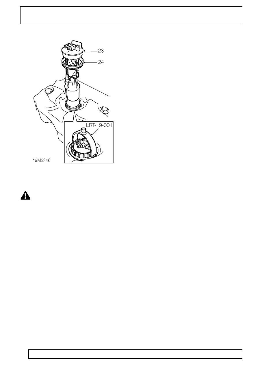
23. Using tool LRT-19-001 remove locking ring

securing pump. Withdraw fuel pump from tank.

WARNING: A quantity of fuel will be
retained in body of pump. Care must be
taken to prevent fuel spillage during above

operation.

24. Remove and discard sealing ring.
25. Fit new sealing ring to pump and fit pump.
26. Fit locking ring and using tool LRT-19-001,

tighten to

48 Nm, 35 lbf ft.

27. Fit fuel feed and return hoses to pump.
28. Fit breather hose and tighten clip.
29. Fit new fuel cut-off valve seals.
30. Fit valve and pipe assembly.
31. Fit heat shield.

Refit

32. With assistance, locate fuel tank and position

cradle.

33. Position jack to support tank.
34. Connect fuel pump multiplug.
35. Raise jack, align cradle and fit and tighten bolts.
36. Raise anti-roll [sway] bar, align straps and fit and

tighten bolts.

37. Tighten anti-roll [sway] bar link bolts
38. Clean fuel pipes, connect pipes and tighten

unions.

39. Secure harness to fuel pipes with clip.
40. Connect vapour separator pipe.
41. Connect breather hose to filler neck and tighten

hose clip.

42. Connect filler hose to fuel tank and tighten hose

clip.

43. Reconnect battery negative lead.
44. Run engine and check for leaks.

SFI

21

REPAIR

FUEL RAIL

Service repair no - 19.60.04

Remove

1. Disconnect battery negative lead.
2. Depressurise fuel system.

See Adjustment,

fuel system depressurise

3. Remove ram housing.

See ram housing

4. Disconnect 8 injector multiplugs.
5. Disconnect fuel temperature sensor multiplug.
6. Position cloth around fuel feed pipe union to

absorb any fuel spillage.

7. Disconnect fuel feed pipe from fuel rail.
8. Plug fuel pipe and rail.
9. Loosen clip securing fuel return hose to fuel rail

and disconnect hose.

10. Plug hose and rail.
11. Remove cloth.
12. Remove 6 nuts securing fuel rail and ignition coil

mounting bracket to inlet manifold.

13. Release ignition coil mounting bracket from inlet

manifold studs and move aside.

14. Release fuel rail and injectors from inlet

manifold.

15. Remove fuel rail and injectors.

Do not carry out further dismantling if component
is removed for access only.

16. Remove 2 bolts securing regulator to fuel rail.
17. Remove regulator.
18. Remove and discard ’O’ ring.
19. Remove 8 clips securing injectors to fuel rail.
20. Remove injectors from fuel rail.
21. Remove and discard ’O’ rings from injectors.
22. Clean lower mating faces on ram housing and

manifold.

23. Lubricate new ’O’ rings.
24. Fit NEW ’O’ rings to injectors. Lightly coat ’O’

rings with silicone grease.

25. Fit injectors to fuel rail.
26. Fit clips securing injectors to fuel rail.

CAUTION: Care must be taken when
refitting the fuel rail and injectors to inlet
manifold to prevent damage to ’O’ rings.

27. Lubricate NEW ’O’ ring of fuel regulator with

silicone grease.

28. Fit ’O’ ring.
29. Fit regulator to fuel rail and tighten bolts to

10

Nm, 7 lbf ft.

Refit

30. Position fuel rail.
31. Secure fuel rail.
32. Position coil bracket.
33. Fit nuts securing coil bracket and fuel rail and

tighten to

8 Nm, 6 lbf ft. .

34. Remove plugs from fuel feed and return pipes

and fuel rail.

35. Connect return hose and secure with clip.
36. Clean feed pipe union.
37. Connect fuel feed pipe and tighten union to

16

Nm, 11 lbf ft.

38. Connect injector and fuel temperature sensor

multiplugs.

39. Fit ram housing.

See ram housing; Refit

40. Reconnect battery negative lead.

19

FUEL SYSTEM

22

REPAIR

RAM HOUSING

Service repair no - 19.70.04

Remove

1. Disconnect battery negative lead.
2. Remove plenum chamber.

See plenum

chamber

3. Disconnect 3 hoses from ram housing.
4. Remove 6 bolts securing ram housing to inlet

manifold.

5. Using a suitable lever and a block of wood,

release ram housing from inlet manifold.
Remove ram housing.

CAUTION: Do not use a mallet to break
sealant joint with inlet manifold.

6. Place a protective cover over inlet bores to

prevent ingress of dirt.

Refit

7. Clean mating faces of inlet manifold and ram

housing.

8. Apply ’Hylomar’ sealant to inlet manifold face.
9. Fit ram housing to inlet manifold.

NOTE: The ram housing can be fitted the
wrong way round. Ensure fuel pressure
regulator hose connection is on correct

side when refitting.

10. Tighten ram housing bolts, working from 2 centre

bolts, diagonally towards 4 outer bolts to

24 Nm,

18 lbf ft.

11. Connect hoses to ram housing.
12. Fit plenum chamber.

See plenum chamber;

Refit

13. Reconnect battery negative lead.

SFI

23

REPAIR

WHEEL SPEED SENSOR - FRONT

Service repair no - 19.80.01

Remove

CAUTION: If a sensor is removed for any
reason, a NEW sensor bush and seal must
be fitted.

1. Disconnect battery negative lead.

2. Release wheel speed sensor multiplug from clip

on inner wing [fender] and disconnect.

3. Raise vehicle on 4 post ramp.
4. Release cable ties securing sensor harness to

chassis and front axle.

5. Clean area around sensor to prevent possible

ingress of dirt.

6. Using a suitable lever, release sensor from

mounting bush.

7. Remove sensor.
8. Position container to collect any brake fluid.
9. Clamp flexible brake hose to caliper.

10. Using 2 spanners, loosen brake pipe to hose

union and disconnect.

CAUTION: Do not allow brake fluid to
contact paint finished surfaces as paint
may be damaged. If spilled, remove fluid

and clean area with clean warm water.

11. Remove nut securing brake pipe to mounting

bracket.

12. Release brake hose from mounting bracket.
13. Remove 2 bolts securing bush retaining plate to

top of hub.

14. Release retaining plate from mud shield and

remove.

15. Remove and discard seal and bush from hub.

Refit

16. Ensure sensor bush and seal mating faces are

clean.

17. Fit sensor bush and seal to hub.
18. Fit retaining plate to hub and secure with bolts.

CAUTION: Apply Loctite 270 to retaining
plate bolts.


Content   ..  25  26  27  28   ..