Defender 90 NAS. Manual - part 17


  Index      Land Rover     Defender 90 NAS - service manual 1997 year


Search            


Content   ..  15  16  17  18   ..


Defender 90 NAS. Manual - part 17


4.0 V8

11

REPAIR

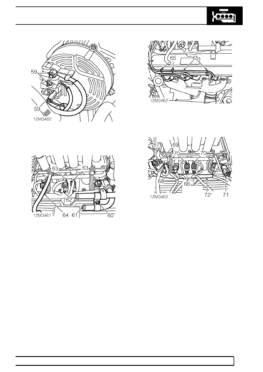
59. Remove 2 alternator terminal nuts and

disconnect Lucar.

60. Remove screw securing heater pipe to bracket.
61. Loosen clip screw and remove heater hose/pipe

assembly from inlet manifold.

62. Remove 2 screws securing engine harness to

RH side of inlet manifold.

63. Disconnect 4 RH injector multiplugs.
64. Disconnect RH rocker cover breather pipe from

ram housing.

65. Release RH bank HT leads from clips and

disconnect from spark plugs.

66. Remove 2 screws securing engine harness to

LH side of inlet manifold.

67. Disconnect multiplug from ECT sensor.
68. Disconnect multiplug from fuel temperature

sensor.

69. Disconnect temperature sensor thermistor.
70. Disconnect 4 LH injector multiplugs.
71. Release ignition coil multiplug from mounting

bracket and disconnect multiplug.

72. Position engine harness aside.

12

ENGINE

12

REPAIR

73. Fit engine lifting tool LRT-12-514 to hoist.
74. Lower hoist and connect lifting chains to engine

brackets.

75. Raise hoist until lifting chains become taught and

use a jact to support gearbox.

76. Remove 6 bell housing to engine bolts.
77. With assistance, raise engine on hoist from

engine compartment.

CAUTION: During the engine removal
procedure ensure that the engine does not
damage any surrounding components.

78. Move engine clear of vehicle and lower onto

work bench.

79. Disconnect lifting chains from engine.
80. Raise hoist and position aside.

Refit

81. Clean engine and gearbox mating faces.
82. Clean dowel and dowel holes.
83. Position hoist above engine.
84. Connect lifting chains to engine.
85. Raise engine from work bench and position

above engine compartment.

86. Position jack beneath gearbox fluid pan and

raise transmission to ease alignment of bell
housing to engine.

CAUTION: Use a block of wood or hard
rubber pad to protect fluid pan.

87. With assistance, lower engine into engine

compartment.

CAUTION: During the engine fitment
procedure ensure that the engine does not
damage any surrounding components.

88. With assistance, align engine to bell housing

dowels.

89. Fit bolts securing bell housing to engine and

tighten to

46 Nm, 34 lbf ft.

NOTE: Align harness brackets to 2
uppermost bell housing retaining bolts.

90. Remove jack supporting gearbox fluid pan.
91. Lower engine hoist ensuring mountings are

aligned with chassis brackets.

92. Disconnect lifting chains from engine eyes.
93. Remove lifting tool LRT-12-514from hoist.
94. Remove hoist from above vehicle.
95. Position engine harness around engine.
96. Connect ignition coil multiplug and secure to

bracket.

97. Connect LH injector multiplugs.
98. Connect gauge temperature thermistor.
99. Connect multiplug to fuel temperature sensor.

100. Connect multiplug to ECT sensor.
101. Connect RH bank HT leads to spark plugs and

secure to guides.

102. Connect RH rocker cover breather pipe to ram

housing.

103. Connect RH injector multiplugs.
104. Align engine harness to RH side of inlet manifold

and secure with screws.

105. Fit heater hose/pipe assembly to inlet manifold

and secure with clip.

106. Align heater pipe to bracket and secure with

screw.

107. Position alternator terminal leads and secure.
108. Route harness down front of engine.
109. Connect Lucar to oil pressure switch.
110. Connect multiplug to camshaft position sensor.
111. Connect radiator bottom hose to heater pipe and

secure with clip.

112. Raise vehicle.

4.0 V8

13

REPAIR

113. Fit nut securing LH engine mounting rubber to

chassis mounting and tighten to

30 Nm, 22 lbf

ft.

114. Fit nut securing RH engine mounting rubber to

chassis mounting and tighten to

30 Nm, 22 lbf

ft.

115. Fit bell housing to engine bolts and tighten to

46

Nm, 34 lbf ft .

116. Remove piece of wood from bell housing access

hole.

117. Align converter to drive plate.
118. Fit bolts securing converter to drive plate and

tighten to

45 Nm, 33 lbf ft.

NOTE: Rotate crankshaft during the above
procedure.

119. Fit bell housing access plate and secure with

bolts tightened to

9 Nm, 7 lbf ft.

120. Clean bell housing cover plate and mating face.
121. Fit plate and secure with bolts tightened to

9

Nm, 7 lbf ft.

122. Connect multiplug to crankshaft position sensor.
123. Fit crankshaft position sensor heat shield and

secure with screw.

124. Position engine harness to LH engine mounting

bracket and secure with cable tie.

125. Connect multiplug to LH knock sensor.
126. Position engine harness to RH engine mounting

bracket and secure with cable ties.

127. Connect multiplug to RH knock sensor.
128. Connect Lucar to starter motor solenoid.
129. Position battery leads to starter motor solenoid

terminal and secure with nut.

130. Position starter motor heat shield.
131. Clean exhaust manifold to front pipe mating

faces.

132. Fit NEW front pipe to manifold gaskets.
133. Connect front pipe to manifold studs and secure

with nuts.

134. Secure starter motor heat shield clip to solenoid.
135. Align starter motor heat shield to RH engine

mounting bracket and secure with bolt.

136. Align RH catalyst heat shield to chassis and

secure with bolt.

137. Lower vehicle.

138. Remove 3 bolts securing engine front lifting

bracket, retain bracket but discard bolts.

139. Position engine lifting bracket to PAS pump,

align to cylinder head and secure with bolts
tightened to

35 Nm, 25 lbf ft.

140. Secure knock sensor harness clip to PAS return

hose.

141. Fit PAS pulley to pump, fit bolts but do not

tighten.

142. Position brake servo pipe and connect to inlet

manifold.

143. Position purge pipe and secure to coolant hose

and harness with cable ties.

144. Fit intake hose to MAF sensor housing and

secure with clip.

145. Position breather pipe ’P’ clip to RH cylinder

head and secure with bolt.

146. Fit plenum.

See FUEL SYSTEM, Repair,

plenum chamber; Refit

147. Remove plugs from fuel return and feed hose

connections.

148. Clean fuel feed pipe connections.
149. Connect feed hose to fuel rail and tighten union.
150. Connect fuel return hose to fuel rail and secure

with clip.

151. Connect heater feed and return hoses to pipes

and secure with clips.

152. Release A/C compressor and position to

mounting bracket.

153. Position heat shield to compressor fixing, fit bolts

and tighten to

25 Nm, 18 lbf ft.

154. Connect compressor multiplug.
155. Clean drive belt and pulley grooves.
156. Using a 15 mm spanner, rotate tensioner

clockwise, fit belt to pulleys and release
tensioner.

157. Tighten PAS pump pulley bolts to

10 Nm, 7 lbf

ft.

158. Fit radiator.

See COOLING SYSTEM, Repair,

radiator

159. Fit bonnet.

See CHASSIS AND BODY, Repair,

bonnet

160. Refill engine oil.

See SECTION 10,

Maintenance, under vehicle maintenance

161. Adjust kick-down cable.

See AUTOMATIC

GEARBOX, Adjustment, kickdown cable
adjustment

4.0 V8

1

SPECIFICATIONS, TORQUE

TORQUE VALUES

Engine V8i

Nm

lbf ft

Crankshaft pully bolt

270

.........................................................

200

Camshaft gear bolt

58

...........................................................

43

Timing cover / coolant pump bolts***

22

...............................

16

Rocker cover to cylinder head

9

..........................................

7

Rocker shaft bracket to cylinder head

38

..............................

28

Spark plug

15

........................................................................

11

Cylinder head bolts:*

Stage 1:

20

...................................................................

15

Stage 2:

then 90

°

...................................................................

then 90

°

Stage 3:

further 90

°

...................................................................

further 90

°

Generator / steering pump bracket to cylinder head

30

........

22

Lifting bracket to cylinder heads

40

.......................................

30

Power steering hose unions:

14 mm

15

.....................................................................

11

16 mm

20

.....................................................................

15

Power steering pump heat shield

25

.....................................

18

Drive belt tensioner

50

..........................................................

39

Drive plate to converter

40

....................................................

30

Drive plate to crankshaft

45

..................................................

33

Drive plate hub aligner to crankshaft socket head screws 85

65

Bell housing bolts

40

.............................................................

30

Access plate

9

.....................................................................

7

Bell housing cover plate

9

...................................................

7

Main bearing cap rear bolts:

Stage 1:

13

...................................................................

10

Stage 2:

72

...................................................................

53

Oil sump drain plug

40

..........................................................

30

Oil sump to cylinder block

23

................................................

17

Starter motor bolts

45

............................................................

33

Starter motor shield

9

..........................................................

7

Oil cooler pipe unions to transmission

30

.............................

22

Tie bar to transmission

45

.....................................................

33

Gearbox breather pipe bracket

9

........................................

7

Engine harness bracket

9

...................................................

7

Engine mountings to engine and chassis

55

.........................

40

Engine mounting rubbers to brackets

30

..............................

22

Compressor heat shield

25

...................................................

18

* Lightly oil threads prior to assembly

** Apply Loctite 222 to threads before assembly

*** Apply Loctite 577 to threads before assembly


Content   ..  15  16  17  18   ..