Defender 90 NAS. Manual - part 16


  Index      Land Rover     Defender 90 NAS - service manual 1997 year


Search            


Content   ..  14  15  16  17   ..


Defender 90 NAS. Manual - part 16


4.0 V8

7

REPAIR

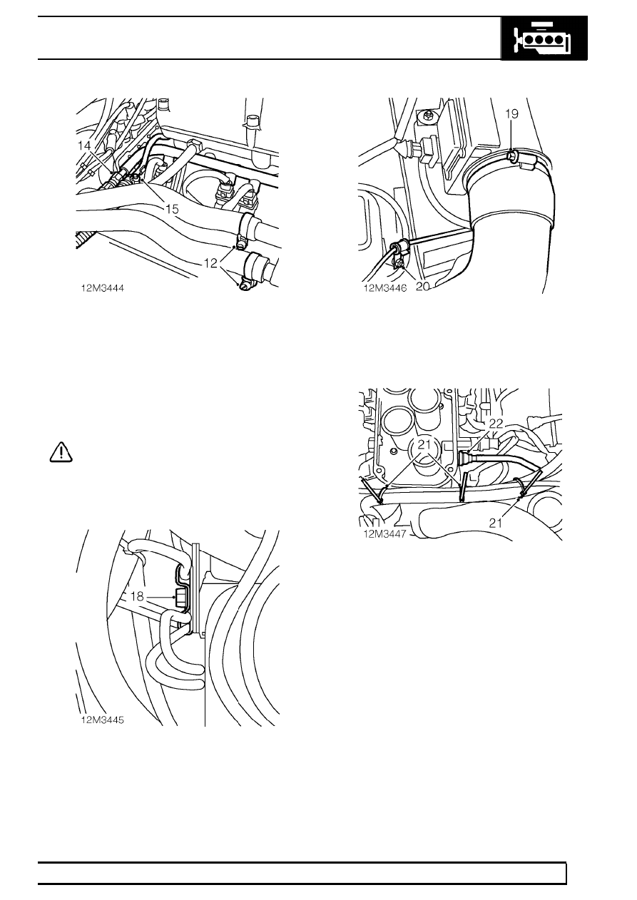
12. Loosen clip screws securing heater return and

feed hoses to pipes and disconnect.

13. Position cloth to collect fuel spillage.
14. Loosen fuel feed hose to rail union, allow fuel to

spill and disconnect union.

15. Loosen clip screw securing fuel return hose to

fuel rail and disconnect hose.

CAUTION: Plug the connections.

16. Remove cloth.
17. Remove plenum.

See FUEL SYSTEM, Repair,

plenum chamber

18. Remove bolt securing 2 breather pipe ’P’ clip to

rear of RH cylinder head.

19. Loosen clip screw securing intake hose to MAF

sensor housing and remove hose.

20. Remove nut securing kick-down cable clip to

rear of LH cylinder head.

21. Remove 3 cable ties securing purge pipe to

coolant hose and harness, position pipe aside.

22. Disconnect brake servo pipe from inlet manifold

and position aside.

12

ENGINE

8

REPAIR

23. Remove 3 bolts securing PAS pulley and

remove pulley.

24. Release knock sensor harness clip from PAS

return hose.

25. Remove 3 bolts securing PAS pump and

position aside.

26. Collect engine lifting bracket.

27. Position engine lifting bracket and secure with 3

(3/8’’ UNC x 1’’ MAX) bolts.

28. Raise vehicle on ramp.
29. Remove 6 nuts securing exhaust front pipe to

manifolds.

30. Remove front bolt securing RH catalyst heat

shield to chassis.

31. Remove bolt securing starter motor heat shield

to RH engine mounting bracket.

32. Release starter motor heat shield clip from

solenoid.

33. Release exhaust front pipe from manifold studs

and remove and discard gaskets.

34. Remove starter motor heat shield.

4.0 V8

9

REPAIR

35. Remove starter motor solenoid terminal nut.
36. Release 2 battery leads from terminal.
37. Disconnect solenoid Lucar.
38. Disconnect multiplug from RH Knock sensor.
39. Remove 2 cable ties securing engine harness to

RH engine mounting bracket.

40. Disconnect multiplug from LH knock sensor.
41. Remove cable tie securing engine harness to LH

engine mounting bracket.

42. Remove screw securing crankshaft position

sensor heat shield and remove heat shield.

43. Disconnect multiplug from crankshaft position

sensor.

44. Remove bolt securing gearbox cooler pipes to

engine sump bracket.

45. Remove 7 bolts securing bell housing closing

plate and remove plate.

46. Remove 3 bolts securing bell housing access

plate and remove plate.

12

ENGINE

10

REPAIR

47. Mark relationship between converter and drive

plate.

48. Rotate crankshaft to access drive plate to

converter retaining bolts.

49. Remove 4 bolts securing drive plate to

converter.

50. Fit suitable piece of wood through bell housing

access hole to retain converter.

51. Remove 2 bell housing lower retaining bolts.

52. Remove nut securing RH engine mounting to

chassis bracket.

53. Remove nut securing LH engine mounting to

chassis bracket.

54. Lower vehicle.

55. Loosen clip screw and disconnect radiator

bottom hose from heater pipe.

56. Disconnect multiplug from camshaft position

sensor.

57. Disconnect Lucar from oil pressure switch.
58. Release harness from front of engine.


Content   ..  14  15  16  17   ..