Defender 90 / 110 / 130. Manual - part 210


  Index      Land Rover     Defender 90 / 110 / 130 - service repair manual


Search            


Content   ..  208  209  210  211   ..


Defender 90 / 110 / 130. Manual - part 210


,:. 

.:- 

..I 

.... 

BODY 

76 

To 

refit. 

10. 

Feed 

the  seat  belt  through  the  trim  aperature. 

Fasten  the  t o p   e d g e  

of 

the  trim 

to 

the  inner 

cant  rail  with  t h e  three spring 

clips. 

15.  Fit  the  seat  and  squab  frame  and  secure  the 

16. 

Fit  the rear  quarter  light  trim. 

seat cushion  t o  the  frame with  the tapes. 

Post trim 

Land  Rover 

only. 

Secure  t h e   lower  e d g e   of  the  trim  with  t h e  
three 

screws  by 

reversing 

t h e   removal 

the  rear  and  centre  screws first 

and  n o t e   that  the  nut  is  t o   the 

plate 

towards t h e  trim. 

12. 

Fit 

the  plastic  retaining  button. 

13. 

Fit  the  seat 

lower  anchorage  and  secure 

with  t h e   special  bolt,  spacer  and  washers,  as 

illustrated.  Tighten  the  bolt  t o  
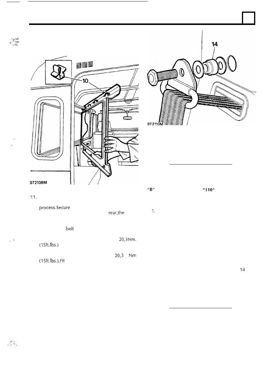
14. 

Similarly, fit  the  seat belt  upper  anchorage and 
tighten 

t h e  

special 

bolt 

t o  

t h e   finisher  t o   t h e   seat  belt 

aperature  in  the  trim  panel  and  the  plastic 
cover 

to 

t h e  anchorage 

bolt. 

To  remove. 

Remove  the  plastic  cover  from  t h e   seat  belt 
upper  anchorage. 

2. 

Remove  the upper  anchorage  bolt  and  fittings. 

3 .  

Carefully  lever-out  t h e   plastic  button  and 
remove  the trim. 

To 

refit. 

4. 

Reverse  the  removal  procedure  ensuring  that 

the  upper  anchorage  bolt  and  fittings  are 
correctly  fitted  and  tightened  t o   t h e   specified 
torque  as  described  in  instruction 

for 

refitting  the rear side trim. 

5. 

Fit  the  plastic  cover  over  the  anchorage  bolt 

and  secure  the  lower  e n d   of  the  trim  with  the 
retaining  button. 

LAND 

WAGON 

Rear 

side 

window trim. 

The  rear 

side 

trim  o n   t h e   Land  Rover 

is 

secured  in  a  similar  manner  t o   that 

of 

t h e  

station 

t h e   fixings  are  common, 

removal 

of 

t h e   inward  facing  seats  will  release  the 

lower  attachment 

of 

t h e   trim  t o   the  side  rail.  The 

squab  frames 

of 

the  individual  inward  facing  seats 

are  each  attached  at  two  points  to  the  side 
bench  type  seat  squabs  are  also  secured  at 

two 

points. 

Rear  quarter light 

To remove. 

To  remove  the  rear  side  trim  of  vehicles  fitted  with 

individual  seats,  the  squabs  only  need  t o   be 

bench  type  seats  are  fitted  the 

complete  seat  and  squab  frame  must  be  removed 
in  order t o  release  the trim  lower attachment. 

Pull 

the  trim  panel  away  from  the  quarter  light 

with  the  fingers thereby  releasing  t h e   retaining 

spring  clips  from the  vertical  rail  and  withdraw 
t h e  panel. 

O n c e  the  trim  lower fixings  have  been  released  and 
the  rear  quarter  light  trim  removed,  the  seat  belt 
upper  anchorage  bolt  assembly  must  b e   removed 
together  with  the  plastic  button  retaining  t h e   trim 
t o   t h e  

post.  The  trim  upper  fixings  are  the 

same  as  t h e  

and  an  upward  tap  with  the 

hand  will  release  it  from  the  inner  cant  rail  enabling 
the trim  t o  b e  removed. 

Fitting  t h e   trim  is  a  reversal  of  the  removal 

is, 

however,  most  important  that  the 

seat  belt  upper  anchorage  fixing  assembly  is  fitted 
correctly 

as  described 

and  illustrated 

under 

instruction  1 4  of  the  Land  Rover 

trim  refitting 

instructions.  The  bolt  must  also  b e   tightened  t o  

Note  that  the  foremost  bushed 

hole  in  t h e  trim,  nearest t h e  

post,  is  not  used. 

To 

refit. 

2. 

Reverse  the  removal  procedure  whilst  ensuring 

that  the  two  metal 

lugs 

locate  behind  the  side 

trim. 

3. 

Align  the  two spring  clips  with  the  vertical  rail 

and  tap  the  panel  into  position  with  the  hand. 

.. 

Grab  handles. 

To  remove. 

Lift  the  plastic  finishers  t o  expose the  securing 

2.  Remove  the  four  screws 

to 

release  the  grab 

screws. 

handle. 

Note:-  In  o r d e r  t o  remove  t h e  trim  above 
t h e  d o o r  between  t h e  

a n d  

station wagons, t h e  

post trim  as 

well  as t h e  g r a b  h a n d l e  must 

be 

trim  above t h e  d o o r  

is 

held  by 

s a m e  a s  used  for t h e  side trim. 

To 

refit. 

4. 

Reverse 

instructions 

and  2. 

HEADLAMPS. 

To 

remove  o r  renew b u l b  o r  light  unit. 

1. 

Remove  the 

two 

screws  and  withdraw  the 

front  side  lamp  lens. 

2. 

Simillarly, remove  the front flasher lens. 

3. 

Remove  the  three  screws  retaining  the  side 
lamp  t o  the wing. 

4. 

Also 

remove  the  screws  securing  the  flasher 

lamp. 

ELECTRICAL 

5.  Ease 

the  side  and  flasher  lamps  from  their 

locations  in  the  wing  and  pull  them  out  as  far 

as 

the  leads  will  allow. 

6 .  

Remove  the 

two 

screws  retaining  the  plastic 

bezel 

to 

the wing. 

7. 

Withdraw  the  bezel  sufficiently  t o   gain  access 

to 

the the  headlamp  retaining  screws. 

From  this s t a g e  pnwards t h e  

p r o c e d u r e  for renewing t h e  h e a d l a m p  bulb 
o r  light  unit  o r  removing  a n d  overhauling 
t h e  headlamp,  is  t h e  s a m e  a s  that  described 
in  section 

86 

page  48 

of 

t h e  current  Land 

Rover  Workshop  Manual 

SLR 

621 

EN 

(English). 

To 

refit. 

8. 

Refitting 

of 

the  plastic  bezel  and  lamps  is  a 

reversal  of  instructions 

t o   7.  Ensure, 

however,  that  when  fitting  t h e   side  and  flasher 
lamps  the  gap  in  t h e   seal  surround  is  located 
at  the  bottom  t o   provide  for  drainage  and 

ventilation. 

9. 

Remember  t o   replace  or  renew  the  rubber 

sealing  washers  over  the  screws  inside  each 
lens. 

Also 

check  that  the  fibre  washers  are  in 

place  under the screw heads  o n  the  outside 

of 

the  lens. 

Printed  in  England  by  Land  Rover  Printing  Services, 


Content   ..  208  209  210  211   ..