Defender 90 / 110 / 130. Manual - part 208


  Index      Land Rover     Defender 90 / 110 / 130 - service repair manual


Search            


Content   ..  206  207  208  209   ..


Defender 90 / 110 / 130. Manual - part 208


... 

... 

T

RAN

S

MI

SS

IO

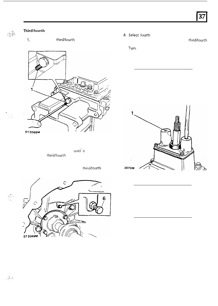
selector rail adjustment 

7. 

Unscrew  the 

stop 

bolt. 

gear  and  screw-in  the  s t o p   bolt 

until  contact 

is 

made  with  t h e  

Slacken  t h e  

s t o p   screw  in  the 

extension  housing. 

selector shaft. 

2. 

Select third  gear. 

3 .  

Tighten  t h e   s t o p   screw 

makes  contact 

with  the 

selector rail. 

4. 

Turn  back  t h e  s t o p  screw o n e  turn. 

5. 

Return  t h e  gear lever t o  t h e  neutral  position. 

6 .  

Slacken  t h e   locknut  on  t h e  

s t o p  

bolt  inside  t h e  bell  housing. 

9. 

back  the  s t o p   bolt  o n e   turn  and  tighten 

the locknut. 

10. 

Return  the gear lever t o  the  neutral  position. 

Bias  spring adjustment. 

1. 

Apply  Loctite  stud  and  bearing  fit  270  t o   the 

bias  spring  screws  and  turn  the  screws 
clockwise  until  the  heads  are  flush  with  the 
t o p  face of the  bias  spring  housing. 

ST 

Gearbox mounting 

1. 

Fit  the  mounting  t o  t h e   extension  housing  and 

secure with  the four  bolts. 

33 

Range 

Land  Rover 

Rover 

Workshop 

Bulletin 

SERVICE  MANAGER 

FEBRUARY  1988 

BULLETIN 

NUMBER 

LAND 

ROVER 

1988 

MODEL 

IMPROVEMENTS 

Further 

supplies of 

this 

can 

he 

Land  Rover  Merchandising  Service 

P.O. Box  534, Erdington  Birmingham  824 OQS 

SERVICE 

Land 

Rover  Service Division 

INTRODUCTION 

INTRODUCTION 

Also 

included  in  the  1988  Year  Land  Rover  model 

improvements  are  the  following  items  which  are 

fully 

described  t o   assist  the  workshop.  The  first 

operation, 

whilst 

not 

being 

part 

of 

the 

improvement 

programme 

is, 

nevertheless, 

continuation 

of 

the  policy  t o   replace  material 

gaskets,  where  practicable,  with  liquid  sealants. The 
opportunity  has,  therefore  been  taken 

to 

include,  in 

this  Bulletin,  the  latest,  most  significant  change 
under  this  policy. 

ALL 

LAND 

ROVER  FOUR  CYLINDER  ENGINES 

Rear  main  bearing  cap sealing. 

change  has  recently  been  introduced  t o   the 

method  of  sealing  the  rear  main  bearing  cap. 

Hitherto  sealing  was  accomplished  using 

shaped 

cork 

packing  strips  o n e   each  side  of  the 

cap.  Sealing  is  now  achieved  by  injecting 

(black) into  the  slots  formally occupied  by  the 

packing  strips. This  material  may  also 

be 

used 

o n  

all 

earlier  engines  where  t h e   caps  were  sealed  with 
packing  strips. 

The 

1. 

2. 

3. 

method 

is 

as 

follows:- 

With  the  sump  removed,  fit  the  main  bearing 

cap  and  tighten  the  bolts  t o   the  correct 
torque,  130-136 

(96- 

Turn  the  crankshaft 

to 

bring  numbers  two  and 

three  pistons  to 

Top 

Dead  Centre 

so 

that  the 

crankshaft  webs  will  not  obscure  the  rear 
bearing  cap. 

Using  a  suitable  applicator,  inject  the  sealant 
into  the  main  bearing  cap  slot  adjacent  t o  the 
bearing  cap 

bolt 

recess  until  it  emerges  from 

the  upper e n d  of  the  slot. 

4. 

5. 

Repeat  instruction  3  o n   the  opposite 

side 

of 

t h e   bearing  cap. 

Remove  surplus  sealant  and  fit  the  sump. 

Note: When  removing surplus sealant from 

the sump gasket  face, ensure that  the 
sealant  is  cleaned-off  level  to the cylinder 
block  machined face. 


Content   ..  206  207  208  209   ..