Defender 90 / 110 / 130. Manual - part 184


  Index      Land Rover     Defender 90 / 110 / 130 - service repair manual


Search            


Content   ..  182  183  184  185   ..


Defender 90 / 110 / 130. Manual - part 184


MANUAL GEARBOX 

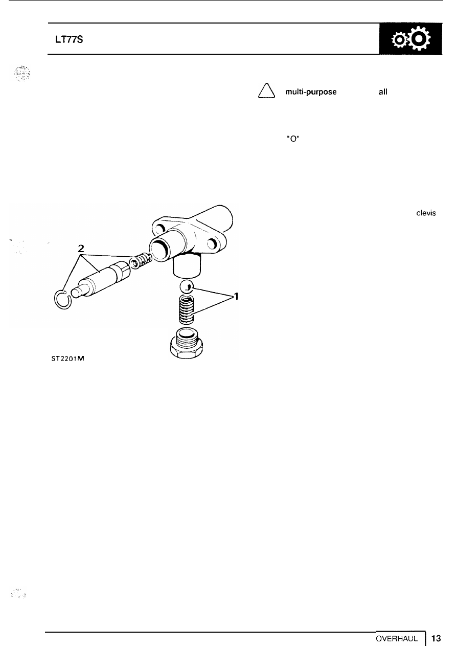
Reverse gear plunger assembly. 

1. 

Remove plug spring and ball. 

2. 

Remove circlip to release plunger and spring. 

3. 

Clean and examine components. 

4. 

Assemble  plunger and spring  with multi-purpose 
grease and secure  with circlip. 

5. 

Lubricate and fit detent ball and spring with light 

oil.  Apply  Loctite 290 to plug threads and fit. 

6. 

Check that  plunger returns when depressed. 

Transfer  gear housing. 

1. 

Remove the four  screws and remove gaiter 

assembly. 

2. 

Disconnect the gear lever from selector fork. 

3.  Retrieve the  non metallic bushes. 
4. 

Remove circlip to release ball and seat and 

withdraw gear  lever. 

5. 

Remove screws from  end cover to withdraw 

cover  and cross shaft. 

6.  Remove selector  fork. 
7. 

Remove detent  spring and plate. 

8. 

Clean and examine ail parts and renew where 
necessary. 

NOTE: 

Assemble the housing  using 

grease on 

moving 

parts. 

9.  Fit internal and external 

"0" 

rings to fork 

assembly. 

10. 

Fit detent spring. 

11.  Fit 

rings to  end cover  and fit to short end 

of  cross  shaft. 

12.  Insert shaft into fork  and secure  end cover with 

screws. 

13. 

Fit Nylon seat, groove downwards, to gear 
lever. 

14. 

Fit gear lever and seat to cross shaft and 
secure with circlip. 

15.  Fit bushes to gear  lever and secure with 

pin and split pin. 

MANUALGEARBOX 

15 

17 

ST 

1.  Gaiter  retaining screw 

off, 

Gaiter. 

3.  Gaiter support plate. 

4. 

Gate  plate. 

5. 

Gasket. 

6.  Split  pin. 
7. 

Clivis  pin. 

8.  Circlip  retaining Nylon seat. 
9. 

Gear  lever ball. 

10.  Nylon seat. 

11.  Cross shaft. 
12.  Gear lever. 
13.  Gear change housing. 
14.  Non-mettalic bushes. 
15.  Counter sunk  screws. 
16.  End cover. 
17.  Detent spring and plate. 
18.  Selector fork. 

19. 

"0" 

rings. 

-

12 

DEFENDER 

MANUAL 

GEARBOX 

SYNCHROMESH ASSEMBLIES 

Third-fourth and fifth gear synchromesh. 

NOTE: the  above assemblies are the 

same except that fifth gear synchromesh 
has a retainer plate. 

1. 

Mark relationship of  inner and outer members. 

2. 

Remove wire clip  from  both sides 

of 

assembly. 

3. 

Remove slippers and separate the two 
members. 

4. 

Examine all parts for  damage and wear 
including wire  clips for tension. 

5. 

Check 

no 

radial movement exists between inner 

members and mainshaft splines. (except fifth 
gear  synchromesh). 

6. 

Examine inner and outer  splines for wear. 

7. 

Examine the  dog teeth on all gears 

for 

wear  and 

damage. 

NOTE: 

shows a tooth 

in 

good condition. 

shows the 

rounded corners of  a worn tooth. 

OVERHAUL 

15 

MANUALGEARBOX 

DEFENDER 

First-second synchromesh 

8.  Repeat instructions 

for third-fourth 

synchromesh. 
Examine step in each 

of 

outer splines. 

10. 

Check  that  the step on both sides of  the 
internal splines are sharp not rounded. 

NOTE: this applies only to splines  on 

selector groove side of  member. 

11. 

Fit 

inner  member to outer 

so 

that the wide 

splines of  inner member are under the  spur 
gear teeth. 

12. 

Fit the slippers and secure  with a spring each 

of 

the synchromesh. 

NOTE: The hooked e n d  of each spring 

must locate in the same slipper with the 

free ends running 

in 

opposite directions 

and 

resting against the remaining slippers. 

13. 

Assemble third-fourth and fifth gear 
synchromesh components as  in instruction 

12. 

NOTE: The back plate for fifth gear  is 

fitted to the rear of the assembly with the 
single tag  locating 

in a 

slot i n  the inner 

member. 

11 

OVERHAUL 


Content   ..  182  183  184  185   ..