Defender 90 / 110 / 130. Manual - part 151


  Index      Land Rover     Defender 90 / 110 / 130 - service repair manual


Search            


Content   ..  149  150  151  152   ..


Defender 90 / 110 / 130. Manual - part 151


Speedlometer illumination 

2. 

Fuel indicator illumination 

3.  Water temperature illumination 
4.  Rear log lamps 
5 .   Number plate lamp 
6.  LH tail lamp 

7. 

LH 

lamp 

8. 

tail lamp 

9. 

side lamp 

10.  LH headlamp dip beam 
11. 

headlamp dip beam 

12.  LH headlamp main beam 
13. 

headlamp main beam 

14.  Interior lamp 

15. 

Stop lamp 

16.  Horn 
17.  LH side repeater 
18.  LH front indicator 
19.  LH 

indicator 

20. 

f r o n t  

indicator 

21. 

rear indicator 

22. 

side repeater 

23.  Auxiliary instrument illumination 
24.  Panel illumination  switch 

25. 

Rear 

fog 

switch 

26. 

lighting switch 

27.  Washer pump 
28.  Steering column switches 
29.  Grouped warning lights (comprising 

items 

to 43) 

KEY 

TO FOUR CYLINDER PETROL DIAGRAM 

30.  Trailer warning light 
31.  Side light warning light 
32.  Rear 

fog warning light 

33.  Main beam warning light 
34. 

Spare position 

35.  Low fuel warning light 
36.  Locked four-wheel drive warning 

37.  Cold start warning light 
38.  Oil warning light 
39.  Charge warning light 
40.  Brake warning light 
41.  Park brake warning light 
42.  Direction indicator warning light 
43.  Seat belt warning light 
44.  Locked four-wheel drive switch 

Clock 
Reversing lamps 

47.  Wiper motor 
48.  Reversing lamp switch 
49a  Brake fluid 

loss 

switch 

(Ninety models only 

49b  Pressure differential warning 

actuator switch 
(One Ten models 

only) 

light 

50.  Heater switch 
51.  Stop lamp switch 
52.  Flasher unit 
53.  Oil pressure switch 

54. 

Brake check relay 
Park brake switch 

56.  Light switch 
57.  Pick-up point for front fog lamps 
58.  Fuses 
59.  Heater motor 

Hazard switch 

61.  Hazard switch illumination 

62. 

Ignition light resistor 

63. 

Starter solenoid 

64.  Spare pick-up point 

65. 

Start relay 

66.  Distributor 
67.  Pick-up point for auxiliary trailer 

68. 

Fuel indicator 

69.  Water temperature indicator 
70.  Oil pressure indicator 
71. 

Oil temperature indicator 

72.  Battery 
73.  Alternator 
74.  Start switch 

75. 

Coil 

76.  Battery condition indicator 
77.  Pick-up point for auxiliary 

instrument illumination 

78. 

Fuel tank unit 

79.  Water temperature transmitter 
80.  Oil pressure transmitter 
81.  Oil temperature transmitter 

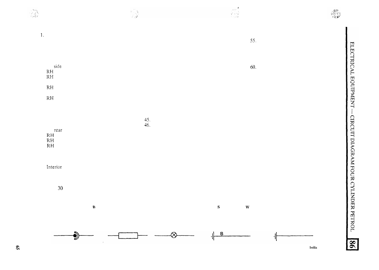
Key to cable colours 

Black 

Green 

Pink 

Light 

N Brown 

Orange  P 

Purple 

Red 

Slate 

Blue 

White 

Yellow 

The last letter 

of a colour code denotes the tracer colour 

Earth connections via cables 

Earth connections via fixing 

Connectors via 

plug 

and socket 

Snap connectors 

Permanent in-line connections 

FOUR CYLINDER 

2.25 

DIESEL, 

L G P  

34 

NY 

44 

++- 

WR 

WB 

NR 

.  . 

.. 

Speedometer illumination 

2. 

Fuel indicator illumination 

3.  Water temperature indicator illumination 
4.  Rear fog lamps (when fitted) 
5 .   Number plate lamp 
6.  LH tail lamp 

7.  LH side lamp 
8. 

tail lamp 

9. 

side lamp 

10.  LH 

dip beam 

11. 

headlamp dip beam 

12.  L H  headlamp main  beam 
13. 

headlamp main beam 

14.  Interior lamp 
15.  Stop lamp 
16.  Horn 
17. 

LH side repeater (when fitted) 

18. 

LH front indicator 

19. 

rear indicator 

20. 

front indicator 

21. 

rear indicator 

22. 

side repeater (when fitted) 

23.  Pick-off  point for auxiliary 

24.  Rear fog switch (when fitted) 
25. 

Washer pump 

26.  Panel illumination switch 
27.  Interior light switch 
28.  Steering column  switches 

29. 

Grouped warning lights (comprising 

instrument illumination  (when fitted) 

items 30 

to 

43) 

KEY 

TO 

FOUR 

CYLINDER 2.25 LITRE DIESEL D I A G R A M  

30.  Trailer warning light 
31.  Side light warning light 
32.  Rear fog warning light 
33.  Main beam warning light 

34.  Spare 

fuel warning light 

36.  Locked  four-wheel  drive  warning 
light 
37.  Cold 

start 

warning light 

38.  Oil warning light 
39.  Charge warning light 

Brake warning light 
Park brake warning light 

42.  Direction indicator warning light 
43.  Seat belt warning light 
44.  Locked  four-wheel drive switch 
45.  Clock (when fitted) 

46.  Reversing lamps (when fitted) 
37.  Wiper motor 
48.  Reversing lamp switch (when fitted) 

49. 

Pressure differential warning 

50.  Heater switch (when fitted) 
51.  Stop lamp switch 
52.  Flasher unit 
53.  Oil pressure switch 
54.  Brake check relay 

55.  Park brake switch (when fitted) 
56.  Pick-off  point  for 

fog lamps 

actuator switch 

(when fitted) 

57. 

Light switch 
Heater 

plugs 

59.  Fuses 
60.  Heater motor (when fitted) 
61.  Hazard switch (when fitted) 
62.  Hazard switch illumination 

(when fitted) 

63.  Starter solenoid 
64.  Spare pick-up point 
65.  Pick-off  point  for auxiliary trailer 
66.  Fuel indicator 
67. 

temperature indicator 

68.  Oil pressure indicator (when fitted) 
69.  Oil temperature indicator (when fitted) 
70.  Battery 
71.  Alternator 
72.  Fuel shut 

off  valve 

73. 

switch 

74.  Ballast resistor 
75. 

Battery condition indicator 

76.  Fuel changeover relays (when fitted) 
77.  Pick-up point for auxiliary instrument 

ion (when fitted) 

Rear tank unit 

79.  Fuel cock switch (when fitted) 

Side tank unit 

81.  Water temperature transmitter 
82.  Oil pressure transmitter (when fitted) 

Oil temperature transmitter (when fitted) 

to cable colours 

B Black 

Green 

Pink 

Light 

N Brown 

0 Orange 

Purple 

Red  S Slate 

White  Y  Yellow 

The last letter 

of 

the colour code denotes the tracer colour 

Connectors via 

and socket 

Snap connectors 

Permanent in-line connections 

Earth 

Earth connections via fixing bolts 

..... 

"I. 

.  . 

... 

.. 

LGP 

+-- 

R Y  

FOUR CYLINDER 2.5 LITRE DIESEL 

65 

76 


Content   ..  149  150  151  152   ..