Defender 90 / 110 / 130. Manual - part 149
4
.
.
.
...
...
. .
.
.
.
.
.
.....
.
,
ault
Rectification
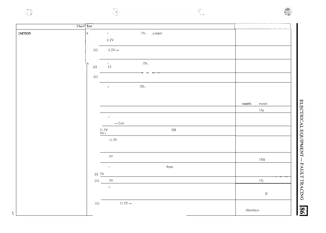
SYSTEM
Connect
0
1
V voltmeter as in Test
f i t a
lead from earth
to
distributor body, with ignition
on and contact breaker points closed:
(i) Below
Remake earth connections between
distributor body and earth
Above
High resistance
or
open circuit in distributor
Checklrepair
or
renew contact
breaker points, base plate screws
earth lead or supply lead
as necessary
Connect
0 20
V voltmeter as in Test
with ignition
on and contact breaker points open:
Above
V-
Continuity
i n
primary windings of coil, supply line and ballast
resistor
if fitted
Carry out Test 15g
Carry
out Test 15f
Zero- open circuit feed
to coil, open circuit primary windings, open circuit
(iii) ballast resistor if fitted
or short circuit in distributor or coil negative lead
Connect
0
20 V voltage as in Test
with ignition
on and contact breaker points open. Remove
coil negative lead
from coil and recheck voltage:
(i) Above 12V- Short circuit in coil, negative lead
or
distributor
Check contact breaker points correctly
fitted, short circuit in condenser
(or
capacitor when ballast resistor fitted)
or
lead;
or
renew
Carry out Test
(ii) Zero - reconnect coil negative lead
Connect
0 20
V voltmeter between earth and coil positive terminal, with ignition on and contact breaker
points closed:
(i) Above 12V
primary windings open circuit
(ii)
- 12V without ballast resistor
If
result
of Test
was above 12V
L.T.
circuit is satisfactory
7V
with ballast resistor
(iii) Below
or zero without ballast resistor
-
Excessive resistance
or open
circuit supply to coil. Leaving the voltmeter connected t o earth, work back through
the supply circuit at the terminals on the ignition switch and solenoid until the
resistance
or
open circuit is located
Renew coil
Fault elsewhere
Rectifv and recheck
(iv) Below
or zero with ballast resistor-
Excessive resistance
o r
open circuit in
supply to coil
Carry out Test
Connect
0
20
V voltmeter between earth and the lead
the ballast resistor
to the coil
positive terminal, with the ignition o n and contact breaker points closed:
- 7V
or
above 12V
-
Fault
in
the ballast resistor to coil lead
Repair or renew lead then re-test
Carry out Test
Below
or zero - Excessive resistance
or open circuit between battery and coil
Connect
0
20 V voltmeter between earth feed lead
to
ballast resistor, with ignition on and
contact breaker points closed:
(i) Above 12V - Fault
in
ballast resistor
Renew and re-test.
satisfactory
fault elsewhere
Zero
or below
Fault in supply circuit from battery. Leaving the voltmeter
connected to earth, work back through the supply circuit at the terminals on the
ignition switch and solenoid until the fault is located.
Rectify and re-test.
I f satisfactory
fault
continued