Defender 90 / 110 / 130. Manual - part 134
 

  Index      Land Rover     Defender 90 / 110 / 130 - service repair manual


Search            


Content   ..  132  133  134  135   ..


Defender 90 / 110 / 130. Manual - part 134


25. 

Lift  the  evaporator  clear  of  the  vehicle  and  place 

on 

a bench  with  a suitable support  underneath  the 

case t o  ensure the heater pipes are not damaged. 

26.  Release  the  nuts  and  remove  the  bracket  from 

underneath the evaporator casing. 

27. 

Remove  the  wire  clip  and  detach  the  dump valve 

located underneath. 

28.  Release  the  seven  self  tapping screws securing the 

outlet  duct  and  carefully  break  the  sealing 

compound  around  the  edge 

of  the  duct  and  pull 

ducting plate away from evaporator body. 

29. 

Remove  the  fifteen  screws  located  around 

t h e  

cover  seam,  Remove  the  old  sealing  compound 
from the body and 

top cover. 

30.  Remove the four screws and four nuts from  the top 

of  the cover. 

31.  From  the  front  of  the  unit  remove  the  two  screws 

adjacent to the low pressure pipe moulding. 

32.  At  the  side 

of  the 

remove  the  two  screws 

adjacent to the air intake aperture. 

33.  Lift  the  top  cover 

off  whilst  feeding  the  blower 

motor wiring and  air control  flap rod  through their 
respective  apertures,  thus  exposing  the  blower 

motor,  heater  matrix  and  air  conditioning 
evaporator matrix. 

... 

Blower motor unit removal only 

Expansion valve removal 

43.  Support  the  suction  pipe 

union  with  suitable 

spanners and release. 

44.  Remove  the  bleed  pipe  retaining  nut  from  the 

suction pipe. 

45.  Remove 

the  spring  clip  retaining  the  expansion 

valve  sensor  pipe  to  the  main  suction  pipe  which 
now 

the expansion valve and high pressure 

pipe.  Place  valve 

on 

bench  and  unscrew  the  high 

pressure pipe from the expansion valve. 

46.  Seal  and  cap  all  apertures;  discard  all  ‘0’ 

rings 

which are renewed 

on assembly. 

Refitting 

47.  Reverse procedures 46 

to 

11 noting that all threads, 

unions, 

rings  are  coated  with 

oil 

prior to fitting. 

NOTE:  Depending  upon  which  unit  has  been 
refitted reverse the appropriate procedures: 
Heater Matrix or Blower Motor 5 

to 3 

Evaporator Matrix 

or Expansion Valve 10 to 6 and 

then  charge  the  air  conditioning  system  as 
previously described with Refrigerant 12. 

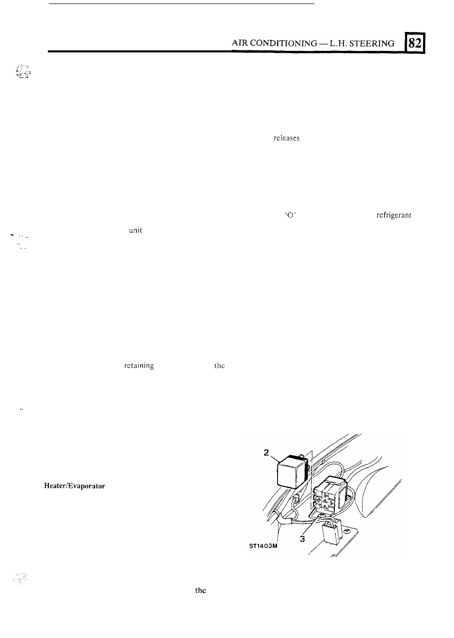
RESISTOR 

BLOCK 

Removal 

34.  Remove the screws 

the  motor unit  to 

casing. 

35.  Release  the  three  bracket  retaining  screws  and 

withdraw motor and impeller. 

36.  Detach 

the star washer, spring clip and impeller. 

37.  Remove the  two nuts from  the  motor  shroud  and 

lift clear. 

1. 

Stop the  engine and  secure the  bonnet 

in  an  open 

2.  Detach the blower motor wiring connector. 
3.  Remove the self tapping  screw and lift the resistor 

position. 

block 

out. 

matrices removal only 

38.  Lift  the  support ptate  and  insulation  pad  from  the 

matrix. 

39.  From  the  bottom  of  the casing,  remove  the  three 

screws  adjacent  to  the  dump  valve  outlet, 

in 

addition to the screws next to the heater pipes. 

40.  Lift  the  evaporator  and  heater  matrices  together 

with  the  supporting  frame  containing  the  air 
direction flap clear of the casing. 

41.  Detach the evaporator matrix by  releasing  the  four 

screws, two at both ends 

of 

the support bracket. 

42. 

Detach  the  heater  matrix  by  removing 

self- 

tapping screw. 

Refitting 

4. 

Reverse procedures 

3 to 1. 

23 

AIR 

CONDITIONING 

R

.

H. STEERING 

EVAPORATOR  BLOWER  MOTOR 

Steering 

models 

Rem 

o v a 

1.  Open and secure the bonnet. 

2.  Release  the  plastic  tie  retaining  the  carburetter 

breather pipe 

to 

the right hand air intake elbow. 

3. 

Remove  the  pulsair  pipe  connected  to  the  air 

intake elbow. 

4. 

Remove the right hand air intake elbow. 

5 .  

Disconnect the clip and blower motor wiring. 

6. 

Release  the  blower  motor  cover  fixings  and 

separate the  casing  slightly  to  allow  the  earth  and 
Lucar connectors to be released. 

7.  Remove the cover ensuring that a mark is made on 

the casing to indicate the correct positioning 

of  the 

blower motor when refitting. 

8. 

Release  the five  self-tapping  screws  and  withdraw 
the blower motor and impeller. It may be necessary 

to  move  the  low  pressure  air  conditioning  pipe 
aside to provide sufficient clearance. 

9.  Remove  the  centre  nut 

on  the  impeller  and 

carefully  ease the impeller  from  the  blower  motor 
shaft. 

Refitting 

Evaporator remove and refit 

R.H. steering models 

For  removal 

of  the  blower  motor  only,  see  section 

“Evaporator Blower Motor”. 

NOTE:  It 

is  only  required  to  evacuate  the  air 

conditioning  system  when  removing  the  evaporator 

matrix or changing the expansion valve. 

Rem 

o v a 

1.  Place  the  vehicle  in  a  ventilated  area  away  from 

2.  Stop the  engine  and  secure  the  bonnet 

in 

an  open 

3.  Disconnect the battery. 

4. 

Unscrew the radiator drain-plug and partially drain 

5 .  

Remove the air-cleaner. 

6.  Remove  the  caps  from  the  compressor  service 

open flames and heat sources. 

position. 

the radiator. 

valves. 

Heater matrix only 

7. 

Fully  close  (turn  clockwise)  the  high  pressure 

8.  Fully  open  (turn 

the 

pressure 

9.  Slowly disconnect  the  low  prcssurc  pipe  from  the 

valve. 

valve. 

compressor rotor lock adaptor plate. 

Remove  the  plastic 

ring  from  the  rotor  lock 

seal.  Cap  and  seal  both  unions  to  prevent  dirt  or 
moisture entering the system. 

pipe to the upper engine bracket. 

12.  Remove the two plastic ties, securing the insulation 

cover 

on 

the  high  pressure  pipe  and  remove  the 

cover. 

13.  Whilst  supporting  both  unions  with  suitable 

.

.


1 1  

10.  Reverse  procedures  9  to  1 ensuring  that  all  seals 

spanners, 

unscrew 

the 

high 

pressure 

air 

24 

are replaced. 

conditioning pipe from the evaporator. 

A

IR CONDITIONING - 

R

.

H

STEERING 

r

-  

Evaporator matrix and expansion valve only 

14.  Evacuate the  air conditioning system as previously 

described. 

15. 

Open  (turn anti-clockwise) 

the compressor service 

valves and disconnect  the gauge set. Cap 

all  pipes 

and gauge connections  to prevent  dirt  or moisture 
entering the system. 

16.  Remove  the  insulating  cover 

on  the  low  pressure 

pipe. 

17.  Whilst  supporting  both  unions  with  suitable 

spanners, 

unscrew 

the 

low 

pressure 

air 

conditioning pipe from the evaporator. 

18.  Cap both  ends to prevent dirt or moisture entering 

the system. 

19.  Remove the two plastic ties, securing the insulation 

cover  on  the  high  pressure  pipe  and  remove  the 

cover. 

20.  Whilst  supporting  both  unions  with  suitable 

spanners, 

unscrew 

the 

high 

pressure 

air 

conditioning pipe from the evaporator. 

82 

Evaporator unit 

21.  Remove  the  self  tapping  screw  securing  the  air 

22.  Disconnect the two ‘Ronco’ thermostat wires. 
23.  Disconnect  the  two  heater  hoses  from 

the  side of 

the evaporator unit. 

24.  Remove  the  vacuum  pipe  from  the  water  valve 

switch. 

25.  Remove  the  clip  and  cable  connection  from  the 

evaporator  air  flap  rod.  Use  a  new  clip  o n  

bly. 

control flap solenoid. 

26.  Disconnect the blower motor wiring connections. 

27.  Remove  t h e   screw  retaining  the  blower  motor 

wiring tot he blower motor housing. 

28.  Remove  the  two  bolts  securing  the  blower  motor 

resistor block to the engine compartment. 

29.  Remove the bolt securing the front support 

to the blower 

motor 

housing. 

30.  From 

the vehicle rcmove the front passenger 

carpet and five self tapping screws which  retain  the 
toe-box cover. 

31.  Release  the  four  bottom  mounting  bracket  bolts, 

ensuring  that 

the  spacing  washers  from  the  two 

innermost  bolts  are  retrieved  from  the  engine 
bulkhead side. 

32.  From  inside  the  engine  compartment  remove  the 

two  13 

upper  evaporator  mounting  bracket 

bolts fitted to the engine bulkhead. 

33.  Lift  the  evaporator  clear  of  the  vehicle  and  place 

on 

a bench  with the blower motor cover facing up. 

34.  Turn  the  evaporator  unit  around  and  remove 

fixings retaining the blower motor housing duct. 

35.  Remove  the  “Ranco”  thermostat  from  the  top 

of 

the unit. 

36.  Remove the seven  self-tapping screws securing 

top and bottom 

of the unit 

37.  Remove the 

screws from  the  right  hand  side 

of the unit. 

38.  Peel  back  t h e   sponge  pad  on  the  outlet  duct  to 

expose the last retaining screw. Remove the 

39.  Remove the two screws 

on the top of  the unit. 

40.  Remove  the  joint  sealant  around 

seam  and 

separate  the  two  halves  of 

evaporator  cover 

assembly 

41.  Remove  the  heater  matrix  from 

evaporator 

casing. 

25 

A

IR CONDITIONING - 

R.H. STEERING 

Evaporator matrix and Expansion valve only 

42.  Release  the  screws  attached  to  the  blower  motor 

retaining plate and remove the plate. 

43.  Remove the blower motor inner housing. 
44.  Remove the bleed-pipe retaining n u t  from  the 

low 

pressure pipe. 

45.  Remove  the  spring  clip  retaining  the  expansion 

valve  sensor  pipe  to  the  low  pressure  pipe  and 
remove  the  expansion  valve  and  high  pressure 
pipe. 

46.  Unscrew the high pressure pipe from the expansion 

valve. 

47.  Seal  and  cap all  pipes  and  connections  to prevent 

dirt  or  moisture  entering  the  system.  Discard  all 

rings, which are renewed 

on 

refitting. 

48.  Release the two nuts adjacent to the dump valve. 
49.  Remove the two evaporator mounting screws from 

each side 

of  the casing. 

50.  Release  the  two 

evaporator  mounting 

bracket  screws  and  pull  the bracket away  from  the 
evaporator. 

51.  Lift the evaporator matrix  from the casing with 

two 

plates and place on a bench. 

Refitting 

52.  Reverse  procedures 

51  to  21,  ensuring  that  all 

threads,  unions  and 

‘0’ rings  are  coated  with 

refrigerant  oil  prior  to  fitting.  Discard  all  old 
rings  and  renew 

on  refitting.  When  reversing 

procedure  31, 

that  the spacing  washers  are 

fitted 

to 

the two innermost bolts. 

NOTE: Depending upon which component has been 
removed,  reverse  the  appropriate  procedure  as 
follows: 
Evaporator  matrix  and  expansion  valve  20  to  2 
Heater matrix 13 to 2. 

26 


Content   ..  132  133  134  135   ..