Defender 90 / 110 / 130. Manual - part 126


  Index      Land Rover     Defender 90 / 110 / 130 - service repair manual


Search            


Content   ..  124  125  126  127   ..


Defender 90 / 110 / 130. Manual - part 126


C

H

A

SS

IS 

A

ND 

B

O

D

76 

11.  Locate  the  packing  strip  and  secure  the  opposite 

runner  with  the  two screws.  Ensure  that  all  three 

screw  heads  are  well  below  the  bottom 

of  the 

runners to prevent damage to the glass. 

12.  Locate the regulator in the window lift channels. 
13.  Carry-out  the  instructions  to  fit  the  mounting 

14.  Fit the door trim, window regulator,  door pull and 

panel. 

bezels. 

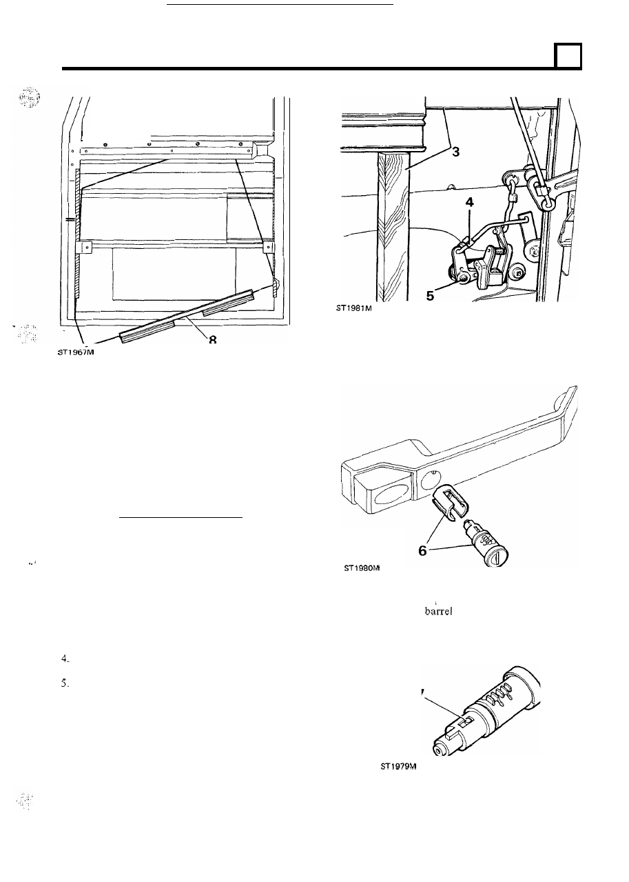
REMOVING LOCKING BARREL -front doors 

To remove 

6. 

Withdraw  the  lock  barrel  from  the  exterior  door 
handle complete with the locking sleeve. 

1.  Remove  the  regulator  handle,  door  pull,  bezels, 

2.  Carry-out  the instructions to remove the mounting 

3 .  

Raise  and  support  the  glass  to  gain  access  to  the 

Release the spring clip and disconnect the rod from 

Remove  the  single  screw  and  withdraw  the  lock 

door trim and weather protection sheet. 

panel. 

latch mechanism. 

the 

lock operating lever. 

7. 

To  remove  the 

from  the  plastic  retaining 

sleeve,  depress  the  spring  loaded  button  and 
withdraw the sleeve. 

lever assembly. 

continued 

19 

CHASS

IS 

A

N

BODY 

Refit the lock barrel 

Note: 

If 

a  new  barrel  is  being  fitted,  check  that  the 

number on the barrel  coincides with the number 

on the 

accompaaing key. 

8. 

Push  the  plastic  retaining  sleeve  over  the  barrel 
until the spring loaded peg locks it into position. 

9.  Fit  the  barrel  and  plastic  sleeve  assembly  to  the 

locking  sleeve  and  insert  into  the  exterior  handle 

reversing instruction 

6 .  

Assemble the lock lever components as illustrated 

and  from  the inside 

of 

the  door panel,  fit  them  to 

the barrel assembly with the single screw. 

11.  Connect  the  operating  rod  to  the  lock  lever  and 

secure with the spring clip, reversing instruction 4. 

12.  Fit  the  mounting  panel  and  weather  protection 

sheet. 

Fit  the  door  trim,  regulator  handle,  door 

pull and bezels. 

20 

Section 
Number 

CONTENTS 

80 

HEATER 

82 

- R e m o v e  and refit 

Drive belt  adjustment 

A I R  C O N D I T I O N I N G  M A I N T E N A N C E  

17 

82 

COMPRESSOR 

- F a n  motors remove and refit 
- C o n d e n s e r  rcmove and refit 

drier remove and refit 

82 

18 

CONDENSER 

82 

- R e m o v e  and  refit 

L.H. 

Steering 

Resistor block 

remove and refit 

- Blower motor 

R . H .  Steering, remove and refit 

EVAPORATOR 

20 

23 

24 

Section 
Number 

86 

CONTENTS 

ELECTRICAL 

E Q U I P M E N T  

Page 

E L E C T R I C A L  P R E C A U T I O N S  

- Polarity 
- H i g h  voltage circuits 

Connectors and 

- B a t t e r y  disconnections 
- B a t t e r y  charging 
- G e n e r a l  precautions 

- Test equipment 

- O v e r h a u l  V8 engine distributor 

Overhaul four cylinder engine distributor 

Ducellier 

Overhaul four cylinder cngine distributor 

Lucas 

- Electronic ignition  distributor type 

V8 engine 

- Electronic ignition  distributor type 

V8 cngine 

- O v e r h a u l  alternator 

all models 

Lucas 

A l  

15-34 and A l  15-45 

- O v e r h a u l  alternator 

all models 

Lucas 

A l t e r n a t o r  functional check 

- D i o d e  

fault symptoms 

- A l t e r n a t o r  fault and diagnosis chart 
- O v e r h a u l  diesel engine starter motor 
- O v e r h a u l  

engine starter motor 

- O v e r h a u l  four cylinder petrol engine starter motor 
- O v e r h a u l  

Paris-Rhone 4 cylinder Diesel engine starter motor 

R c m o v c  and refit  2.5 Turbo 

Diesel engine starter motor 

Overhaul Lucas 

starter motor 

L a m p s  

Overhaul wiper motor 


13 

20 
24 
28 
29 
29 
30 
34 
37 

41 
44 
45 
48 
52 

E L E C T R I C A L  E Q U I P M E N T  

F A U L T  T R A C I N G  

- Introduction 
- Charging 
- Ignition system 
- Starter system 

54 
55 
56 
60 

CIRCUIT DIAGRAMS 

- F o u r  

cylinder petrol engine 

- 2.25 litre diesel engine 
- 2.5 litre diesel engine 

cylinder engine 

- Composite circuit diagram 

1986 onwards all models 

Dim-dip circuit diagram 

- Twin T a n k  

Twin pumps 

- O p t i o n a l  equipment circuit diagrams 

64 
66 
68 

70 
72 
74 
75 
76 

II 


Content   ..  124  125  126  127   ..