Defender 90 / 110 / 130. Manual - part 124


  Index      Land Rover     Defender 90 / 110 / 130 - service repair manual


Search            


Content   ..  122  123  124  125   ..


Defender 90 / 110 / 130. Manual - part 124


C

H

A

SS

IS AND 

BODY 

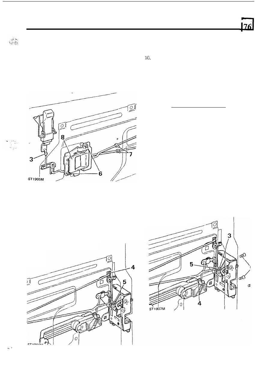
RENEW  REMOTE  CONTROL  LEVER 

rear  side 

door 

To 

remove 

1.  Remove the door trim, door pull, regulator handle 

2.  Peel-back sufficient of the weather protection sheet 

3.  Remove the spring clip and disconnect  the control 

and bezels. 

to gain access to the remote lever. 

rod from the locking button. 

Fitting control lever 

9. 

Fit  the  plastic  retaining  clips  to  the  rod  assembly 

Connect the control rods 

to 

the latch assembly and 

11.  Fit  the  plastic  retaining  rod  clips  to  the  mounting 

12.  Connect  the  control  rod  to the locking  button  and 

13.  Re-seal  the  weather  protection  sheet  and  fit  the 

into position and secure with  the two screws. 

secure with the clips. 

panel. 

secure with the clip. 

trim panel, regulator handle, door pull and bezels. 

REMOVE  DOOR  LATCH  ASSEMBLY 

rear  side 

door 

To remove 

1.  Remove  the  door  pull,  regulator  handle,  bezels 

2.  Peel-back sufficient 

of  the weather protection sheet 

3 .   Release the remote control lever rod from the latch 

4.  Disconnect the door outer handle control rod from 

and door trim. 

to reveal the latch. 

assembly. 

the latch assembly. 

5. 

Disconnect the door locking button remote control 

6. 

Remove  the  three  retaining  screws  and  withdraw 

4.  Release  the  spring  clip  and  disconnect  the  short 

locking  button  control  rod  from  the  latch 

mechanism. 

5. 

Disconnect  the  long  remote  control  rod  from  the 

latch assembly. 

6 .  

Remove  the  two  screws  securing  the  remote 

control lever to the mounting panel. 

7. 

Release  the control  rods from  the plastic retaining 

clips located in the mounting panel. 

8.  Withdraw  the  remote  control lever  and rods from 

the door. 

rod from the latch mechanism. 

the latch assembly from the door. 

continued 

11 

76 

Fitting the latch 

7.  Fit the latch assembly  to the door and secure with 

the  three  screws,  noting that  the uppermost  screw 
is longer. 
Connect  the  remote  control  levers  to  the  latch 
mechanism reversing instructions 

3 , 4  and 

5. 

9. 

Re-seal  the  weather  protection  sheet  and  fit  the 

regulator handle, door pull, door trim and bezels. 

C

HASS

I

S AN

BODY 

REMOVING DOOR GLASS 

rear side door 

To remove 

1.  Disconnect the door check rod from the door post. 

2.  Remove  the  regulator  handle,  door  pull,  bezels 

3.  Remove the weather protection sheet. 

5 .  

Disconnect and remove the door locking button. 

6. 

Disconnect  the  control  rods  from  the  latch  and 

and door trim. 

4.  Remove the window regulator assembly. 

door outer handle mechanism. 

Remove  the  four  screws  retaining  the  mounting 

panel  to  the  door and  remove  the panel  complete 
with rods and control lever. 

8. 

Remove the single self tapping screw 

to 

remove the 

water channel. 

9.  Remove the door check torsion  bar. 

10.  Remove  the  door check  rod  by  bending  back 

t h e  

end stop to enable the rod to be withdrawn. 

12 

C

HASSI

A

N

D B

ODY 

11.  Remove  the  four  self-tapping screws 

two  each 

12.  Remove  the  inner  and  outer  weather  strips  from 

side-securing the glass lower channel. 

the door sill. 

12 

12M 

13.  Lower  the  glass down  to  the  bottom  of  the  door, 

lift  the  glass  over  the  lower  edge  and  withdraw 
from the door 

14.  Remove  the  lift  channel  from  the  glass,  if 

necessary. 

. . 

Fitting 

glass 

Fit  the  lift channel  to  the  new  glass if  not  supplied 

16.  Insert  the  glass  into  the  lower  channels  and 

already fitted. 

carefully push the glass up to the top of  the frame. 

17.  Secure  the  lower  channels  with  the  four 

tapping  screws.  Ensure  that  the  screw  heads  are 
screwed  down  firmly  below  the  bottom  of  the 

channels to prevent damage to the glass. 

18. 

Fit the door check rod 

and 

bend 

the end stop back 

to the closed position. 

19. 

Fit  check stop torsion  bar  and secure with  the two 
nuts and bolts. 

20.  Fit  the  water  channel  and  secure  with  the  single 

self-tapping screw. 

21.  Fit  the  mounting  panel  complete  with  rods  and 

remote control lever. 

22.  Connect  the  control  rods  to  the  latch  and  door 

outer handle mechanism. 

23.  Fit the door locking button  and connect the control 

rod. 

24.  Fit the window regulator. 
25. 

Fit the door inner and outer sill weather strips. 

26.  Fit and 

the weather protection  sheet. 

27.  Fit  the  door  trim,  regulator  handle,  door 

and 

28.  Connect the door check rod to the door post. 

bezels. 

13 

C

H

A

SS

IS 

AND 

B

OD

REMOVING MOUNTING PANEL 

front doors 

To remove 

Remove  the  door  trim,  window  regulator,  door 

pull, bezels and weather protection sheet. 

2.  Remove  the  four  screws  securing  the  window 

regulator to the mounting panel. 

3. 

Remove  the  five  screws  securing  the  mounting 

panel to the door frame. 

4. 

Release the remote control lever rod from the latch 

mechanism  and  from  the  plastic  clip 

in  the 

mounting panel. 

5 .   Slide the window regulator arm from the mounting 

panel  channel  and  remove  the  panel  with  the 
remote control lever and rod. 

Fitting mounting panel 

6 .  

Engage the window regulator arm in  the mounting 
panel channel. 

7. 

Connect  the  remote  control  rod  to  the  latch 

mechanism and secure with the clip. 

8. 

Fit  the  mounting  panel  and  retain  with  the  five 
screws. 

9. 

Secure the window regulator to the mounting panel 

with the four screws. 

10. 

Raise  and  lower  the  window  to  check  for  free 

movement. 

11. Fit  the  weather  protection  sheet,  door  trim, 

window regulator handle, door pull and bezels. 

REMOVING  DOOR  LOCKING  BUTTON 

front 

doors 

To remove 

1.  Remove  the door trim  regulator  handle,  door pull 

2.  Peel back sufficient 

of  the weather protection sheet 

3. 

Release  the  spring  clip  and  disconnect  the 

4. 

Remove the  two screws and withdraw  the  locking 

and bezels. 

to expose the mechanism. 

operating rod from the latch mechanism. 

button assembly. 

continued 

14 


Content   ..  122  123  124  125   ..