Defender 90 / 110 / 130. Manual - part 83
FIVE
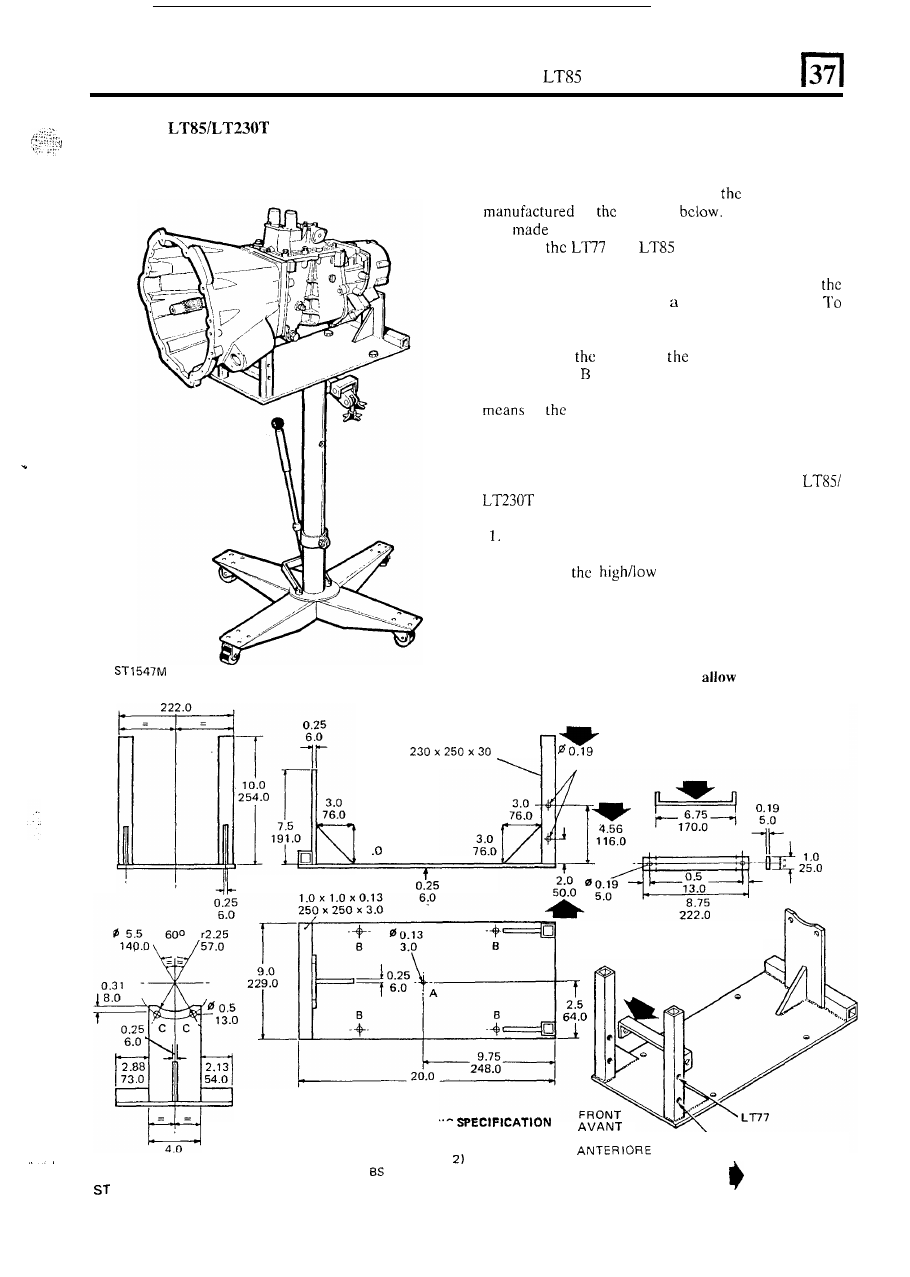
SPEED GEARBOX
REMOVE
MAIN GEARBOX AND
Cradle
for removing gearbox
The gearbox should be removed from underneath the
vehicle, using a hydraulic hoist, as illustrated;
a cradle
for locating the gearbox on to
hoist can be
to
drawing
If a similar cradle
was
for the LT77 gearbox,
it
can be modified to
suit both
and
gearboxes by making the
modifications shown by the large arrows.
Manufacture a cradle
to t h e dimensions given in
drawing
and
attach
it
to
transmission hoist.
achieve balance
of the transmission unit when mounted
o n the transmission hoist,
it
is
essential
that
point
A
is
situated over
centre
of
lifting hoist ram. Drill
fixing holes
to suit hoist table. Secure the
transmission unit to the lifting bracket
at
point
C, by
of
lower
bolts
retaining
t h e
transfer gearbox
rear
cover.
TRANSFER
BOX
Refer to the Removal instructions for the LT77
gearbox page 1. The method
for
removing the
gearbox assembly is similar, except for the
following.
It is not necessary to remove the engine fan cowl.
2. Remove the air cleaner.
3. Remove
selector
housing from the
4.
Use
t h e
cradle and hydraulic hoist already
transfer box.
described,
to remove the gearbox.
NOTE: It
may
be necessary to remove the
transmission brake drum
to
removal of the
8.75
gearbox
assembly.
1.0 x 1.0 x 0.13
.
5.0
1
3.0
76
508.0
MATERIAL A N D WELDING
VORDER
LT85
..
.
Steel
Plate
BS 1449 (Grade 4 or 14)
102.0
Tu
be
BS
4848 (Part
Arc
Welding
5135
= MODIFICATION
538M
61