Defender 90 / 110 / 130. Manual - part 72
LT77
FIVE SPEED GEARBOX
The latest model gearbox employs a spring-loaded
biased gear change lever assembly and the following
instructions
(212 to 236) include the fitting and
adjustment of this arrangement.
Gear selector housing
212. Refit the gear selector rollers, pin and new circlip
ensuring circlip is not expanded beyond minimum
necessary to obtain entry.
213. Lubricate t h e gear selector housing shaft with
light
oil and fit a new
ring.
214. Insert shaft through the large blanking plug
orifice, ensuring the shaft indent is uppermost.
215. Place the gear selector housing into protected vice
jaws and fit the selector yoke to the shaft, using a
suitable pin punch and new
roll pin. Remove the
housing assembly from the vice on completion.
216. Fit the reverse switch and large blanking plugs.
Coal plug threads with Loctitc 290 and tighten to
217. Refit the fifth gear
spool retainer and tighten the
bolts and washer 7
(5 Ibf
and
fit
a new
nylon insert into t h e trunnion housing and secure
with a n e w circlip.
218. Invert the gear selector housing and fit the
trunnion housing to the sclector
ensuring
the locating bolt aligns with the shaft indent. Coat
the bolt threads with Loctite
Tighten bolt to
the specified torque.
219. Fit a new gear lever gasket and locate the gear
lever
housing, spring washers and bolts. Tighten
bolts
to the specified torque.
220. Fit the two bias spring adjustment screws and lock
nuts.
221. Place the bias spring in position with the spring
legs either side of the gear lever housing and
retain with a roll-pin.
222. Coat the upper and lower spheres of the gear
lever shaft with
Q.5848
or Shell
R I and locate the lever
in t h e gearbox
and retain with the bolt and special lock washer.
223. Using a screw driver lift the bias spring legs over
the gear lever crosspins.
Do
not overstress the
spring legs.
the main gear lever with the
gaiter. Align the marks made when dismantling.
the
10
‘Nyloc’ n u t .
224. Select first
or second gear. It may bc necessary to
rotate the mainshaft whilst manipulating the gear
lever.
Locate the reverse gear plunger assembly on the
right hand side viewed from rear, giving sufficient
load
on the trunnion to eliminate side play. Whilst
maintaining a light
pressure, measure the
and gear selector casting. Add 0,6
the
measured figure and select suitable thickness
shims to equal the total.
226. Remove the reverse plunger assembly, fit the
required thickness
and refit the plunger
assembly, spring washers and bolts. Tighten to the
specified torque.
the specified torque.
between
casting
227. Fit the fifth gear stop o n
the left hand side viewed
from the rear, giving sufficient load
on the
trunnion
to
eliminate
side
play.
Whilst
maintaining a light finger pressure, measure the
clearance between t h e plunger assembly casting
and gear selector casting. Add
to the
measured
and select suitable thickness
shims to equal
the total.
228. Remove the fifth gear stop,
fit
the required
thickness
Refit the gear stop assembly,
spring washers and bolts. Tighten bolts to the
specified torque.
229.
To adjust the bias springs with the unit completely
assembled, engage either third or fourth gear.
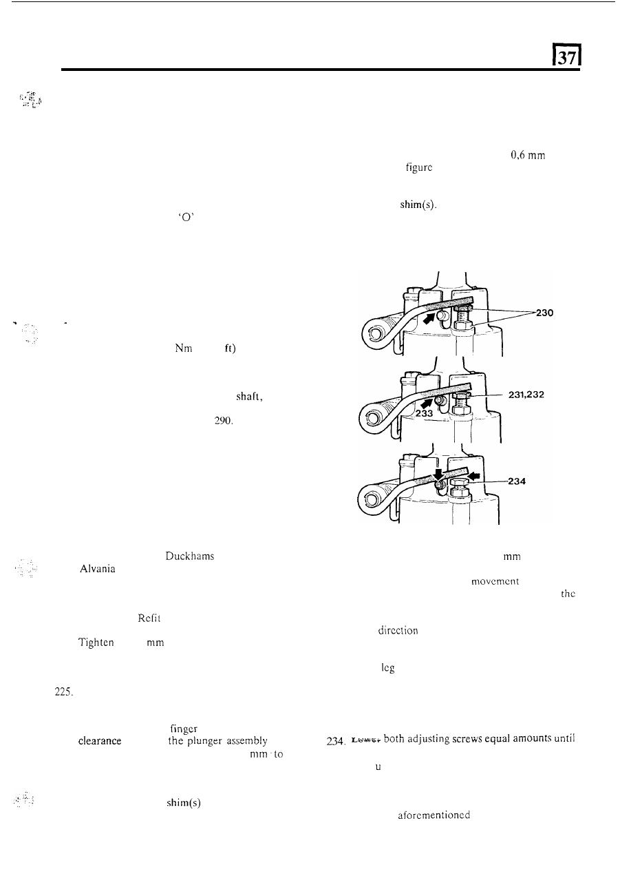
230. Adjust the two adjusting screws until both legs
of
the spring are approximately
0,5
clear of the
cross-pin in the gear lever. This should allow a
certain amount
of radial
of the gear
lever without the cross-pin contacting either of
spring legs.
231. Apply a slight load to
t h e
gear lever knob
in
a left
hand
to
position the gear lever at one
extreme of the radial play. Adjust the right hand
adjusting screw downwards until the right hand
spring
just makes contact with the cross-pin
o n
the right hand side.
232. Repeat instruction 229
in the opposite direction.
233. At this stage, radial play will still be present, but
at the other extreme the cross-pin should just
make contact with the spring leg on the other side.
the radial play is just eliminated. Tighten
lockn ts.
235. Return gear lever to neutral position and rock
across the gate several times. The gear lever
should return
to the third and fourth gate. If not,
repeat the
procedure.
236. Fit the rubber gaiter and secure with a strap.
17