Defender 90 / 110 / 130. Manual - part 70


  Index      Land Rover     Defender 90 / 110 / 130 - service repair manual


Search            


Content   ..  68  69  70  71   ..


Defender 90 / 110 / 130. Manual - part 70


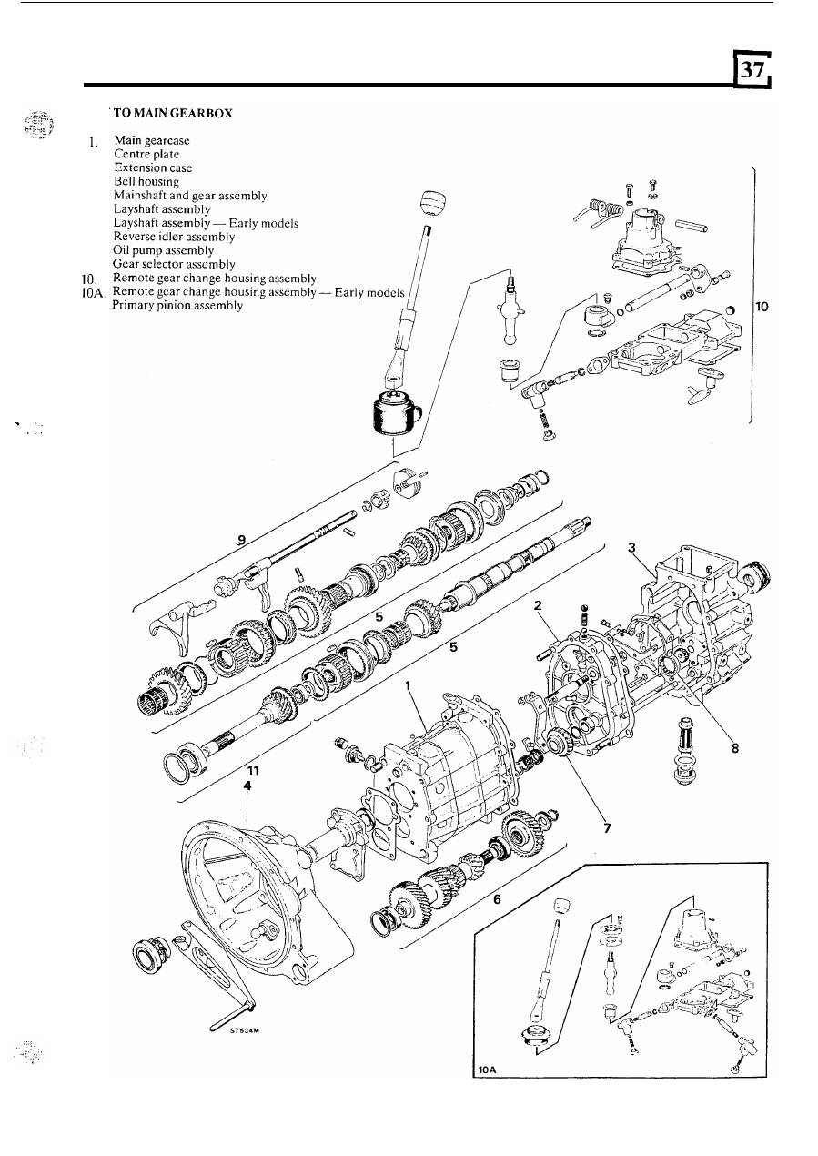
LT77 FIVE SPEED GEARBOX 

KEY 

2 .  
3. 

4. 

5 .  
6. 

6A. 

7. 

8. 

9. 

11. 

. .  

93.  Refit  the  slippers  and  locate  the  slipper  rings  to 

each  side 

of  the  assembly,  ensuring  that  the 

hooked  ends  of  both  slipper  rings  are  located  in 
the  same  slipper;  but  running  in  opposite 
directions  and  finishing  against 

other  t w o  

slippers. 

FIVE SPEED GEARBOX 

93 

94.  Assemble  the  third  and  fourth  synchromesh 

assembly and  ensure  the  hooked ends are located 
in the same slipper; and run 

in opposing directions 

and finally locate against the other two slippers. 

95.  Refit  the  fifth  synchromesh  hub  assembly  again 

ensuring the 

ends of  the rings are located 

in  the  same  slipper,  but  running 

in  opposite 

Fit 

t h e  

backplate  onto the  rear  of  the 

synchromcsh hub asscmbly. Ensure 

tag on the 

backplate locates 

in 

the slot on the hub. 

96.  Check  the  wear  between 

all 

the  synchromesh 

cones  and  gears  by  pushing  the 

against 

gear and measuring  the gap between  the gear and 
cone.  The  minimum  clearance  is 
(0.025 in). 

If  this  clearance  is  not  met,  f i t   new 

synchromesh cones. 

First 

gear 

bush end-float 

97.  Manufacture  a spacer to the dimensions provided 

in  the  illustration,  this  will  represent  a  slave 
bearing 

10 

m m 

16-52 

98. 

the  second  gear  needle  bearing 

with 

light 

oil  and 

fit 

the  bearing,  second  gear  and 

synchromcsh cone to the  mainshaft.  It  should  be 
noted  that the second gear synchromesh cone has 
larger  slipper  slots  than  the  other  synchromesh 

99.  Fit 

first  and  second  synchromesh  hub 

assembly with the selcctor fork annulus to the rear 
of the mainshaft. 

100. 

Fit  the  first  gear  bush  and 

bcaring  spacer 

and  a  new  circlip  to  the  mainshaft.  When  fitting 
the circlip, care  must  be  taken  to ensure 

it 

is  not 

opened 

(stretched) 

beyond 

the 

minimum 

necessary 

to pass over 

t h e  

shaft. 

101. 

Press  the 

bearing  spacer  back  against  the 

circlip  to  allow  the  bush  maximum  cnd-float. 
Measure  the  clearance  between  the  rear  of 
first  gear bush  and front face 

of 

slave bearing 

spacer with  a  feeler gauge.  The clearance  should 
be within 

0,005 to 

0,055 mm. The first gear  bush 

is  available  with  collars  of  diffcrcnt  thickness. 
Select  a  bush  with  a  collar  to 

t h e  

required 

end-float.  The  bush  must  be  free to rotate  easily 

with 

required cnd-float. 

102. 

Remove the circlip, slave bearing spacer and  first 

gear bush from the mainshaft. 

103.  First  gear  bushcs  are  available  in  the  following 

sizes: 

Part 

N o .  

Thickness 


104.  Having  selected  a  suitable  first  gear  bush, 

lubricate  the  needle  bearing  and 

fit 

to  the  first 

gear. 
Fit  the  selected  bush  to  t h e   first  gear  and 

u y  

gear assembly to the mainshaft. 

106.  Using  tools 

and 

refit  the  centre  bearing  and  circlip 

to 

the 

mainshaft. 

107.  Invert  the  mainshaft, 

the  third  gear 

needle roller  bearing with  light  oil, 

fit 

to the front 

end of  the mainshaft. 

FIVE S

PEED 

G

E

A

R

BOX 

.  . 

108.  Fit  the third gear to the mainshaft;  and locate the 

third gear synchromesh cone 

to 

the third gear. 

109.  Fit  the 

synchromesh  assembly  (with 

the  longer  box 

of 

synchromesh  hub  to  the 

front of  the gearbox) to the mainshaft. 

110.  Fit  the  spaccr  and  bearing  to  the  front  of  the 

mainshaft. 

Input 

shaft 

111.  Using  tool  MS47  and  any  suitable  tube,  refit  a 

112. 

Fit  the  input  shaft  bearing  using  tools 

new pilot  bearing track to the input shaft. 

and 

Reverse Gear and Shaft 

113.  Fit  a  new  circlip  to  the  rear  of  the  reverse  idler 

gear,  ensuring  that  the  circlip  is  not  stretched 
beyond  the  minimum  necessary  to  pass  over  the 
shaft. 

114. 

Lubricate 

with 

light  oil  and 

fit 

both  needle  roller 

bearings.  Fit  the  shorter 

bearing  to  the 

rear of  the reverse idler gear. 
Fit  a  new  circlip  to  the  front  of  the  reverse  idler 

gear. 

Extension case 

116.  Using a suitable  press, 

fit 

a  new  fcrrobcstos bush 

to 

the  case,  ensuring 

two  drain  holes  are 

towards 

bottom 

of  the case. 

117.  With the aid  of  tool 

fit 

a new oil seal to 

the 

rear of  the extension case. Ensure the seal lips 

are  towards  the  ferrobestos  bush.  Lubricate 
seal lips with a suitable 

SAE 140 oil. 

118.  Assemble  and  fit  the  fibre  oil  pump  gears  to  the 

oil  pump  cover,  whilst  ensuring  the  centre  rotor 
squared drive faces 

t h e  layshaft. 

119 

117 

119.  Fit  the  three  bolts  and  spring  washers  to  secure 

the  oil  pump  covcr;  and  tighten  to 

specified 

torque. 

120.  Ascertain  that  the  oil  pick  up  pipe  is  free  of 

contamination 

or blockage. 

121. 

Fit a new oil filter, fibre gasket and tighten plug to 
the specified torquc. 

Centre plate 

122. 

Fit  the  ccntre platc  to a  suitable stand and secure 

123.  Place  the  new  mainshaft  and  layshaft  bearing 

124.  Lightly lubricate the selector shaft with a light oil. 
125.  Take the selector shaft complete with the first and 

second  selector  fork,  front  spool  and  third  and 
fourth  selector fork; engage both selector forks 

in 

their  respective  synchromesh  slccvcs  on 
mainshaft,  simultaneously  engaging 

sclcctor 

shaft and mainshaft assemblies 

the centre plate, 

whilst  rotating  the  fifth  gear selector  pin  to  align 
with the slot 

in the centre plate. 

with two slave bolts. 

tracks to the centre plate. 

126. 

Fit 

the layshaft 

to the centre plate. 

127. 

Rotate 

shaft  and 

reverse  crossover  lever forks 

to  correctly  align  to 

the  reverse  pivot  shaft.  Reposition  the  selector 
shaft and locate the lever between the fork 

on the 

reverse  gear pivot  shaft.  Insert pivot  pin  and 

fit 

new circlip, ensuring that it is not  opened beyond 
the minimum  necessary to pass over the shaft. 

11 

FIVE SPEED GEARBOX 

126 

128.  Fit  t h e  slipper pad  to  the  reverse  lever. 

If  a  new 

reverse lever pivot  shaft  has been 

it will 

be 

necessary  to  ascertain  that  its  radial  location  is 

with 

the 

reverse 

pad 

slipper 

The  radial  location  is 

determined during initial assembly. 

129.  Fit  the  reverse  gear  spacer  and  reverse  gear 

assembly,  locating  the  slipper  pad  lip  to 

t h e  

reverse  gear  groove.  Engage  the  reverse  gear 
shaft  from  the  underside  of  the  centre  plate, 
ensuring the roll  pin  is aligned with  the slot 

in 

centre plate casing. 

12 

spring  with  light  oil,  and 

fit  to  the  top of  centre 

130.  Prior  to  assembly  lubricate  the  detent  ball  and 

plate.  Smear Hylomar PL32 or Loctite 

290 to the 

plug  threads  and  screw  the  plug  flush  with  the 
case.  Stake  the  plug  to 

rotation  using  a 

suitable centre punch. Release the 

bolts. 

131.  Locate  the  fourth  gear  synchromesh 

to  the 

synchromesh assembly. 

132.  Fit the input shaft to the mainshaft. 
133.  Fit  the  reverse  gear  spacer 

to 

reverse  gear 

134. 

Fit a new gasket to the centre plate. 

shaft. 

Main gearbox casing 

135.  Insert  a  new  plastic  oil  trough  to  the  back  of  the 

main  gearbox  casing,  ensuring  the  open  trough 
faces the top 

of  the case. 

136.  Carefully  lower  the  gearcase  into  position  over 

t h e  

gear  assemblies. 

DO  N O T  

USE 

FORCE. 

This operation can be assisted by  the use of  two 

100 

guide  studs.  Ensure  the  centre  plate 

dowels  and  selector  shaft  arc 

in  their 

respective locations. 

137.  Fit  the  layshaft  and  input  shaft  bearing  outer 

tracks. 

138.  Using 

35 

slave bolts and plain  washers 

to 

prevent  damaging 

rear  face 

of  the  centre 

plate,  evenly  draw  the  gcarcase  into position  on 
the plate. 

139.  Fit  the  locating shaft front spool to  the top 

gearcase using  Hylomar PL32 to seal between  the 
spool  and  gearcase.  Smear  Loctite  290  or 
Hylomar  PL32 

to  the  bolt  threads,  tighten  bolts 

and spring washers to the specified torque. 

140.  Manufacture  a  layshaft  support  plate  and  plain 

washer  to  the  dimensions  provided  in  the 
illustration. 

141.  The  layshaft  support  plate  is  fitted  using  two 

25 

bolts  and  washers  to  the  front  of  the 

-- 

gearbox,  with  the  plain  washer  situated  between 
the  support  plate  and  layshaft.  The  plate  also 
retains the input shaft bearing outer track. 


Content   ..  68  69  70  71   ..