Defender 90 / 110 / 130. Manual - part 54


  Index      Land Rover     Defender 90 / 110 / 130 - service repair manual


Search            


Content   ..  52  53  54  55   ..


Defender 90 / 110 / 130. Manual - part 54


PETROL F

U

EL SYS

TEM 

... ,.. 

... 

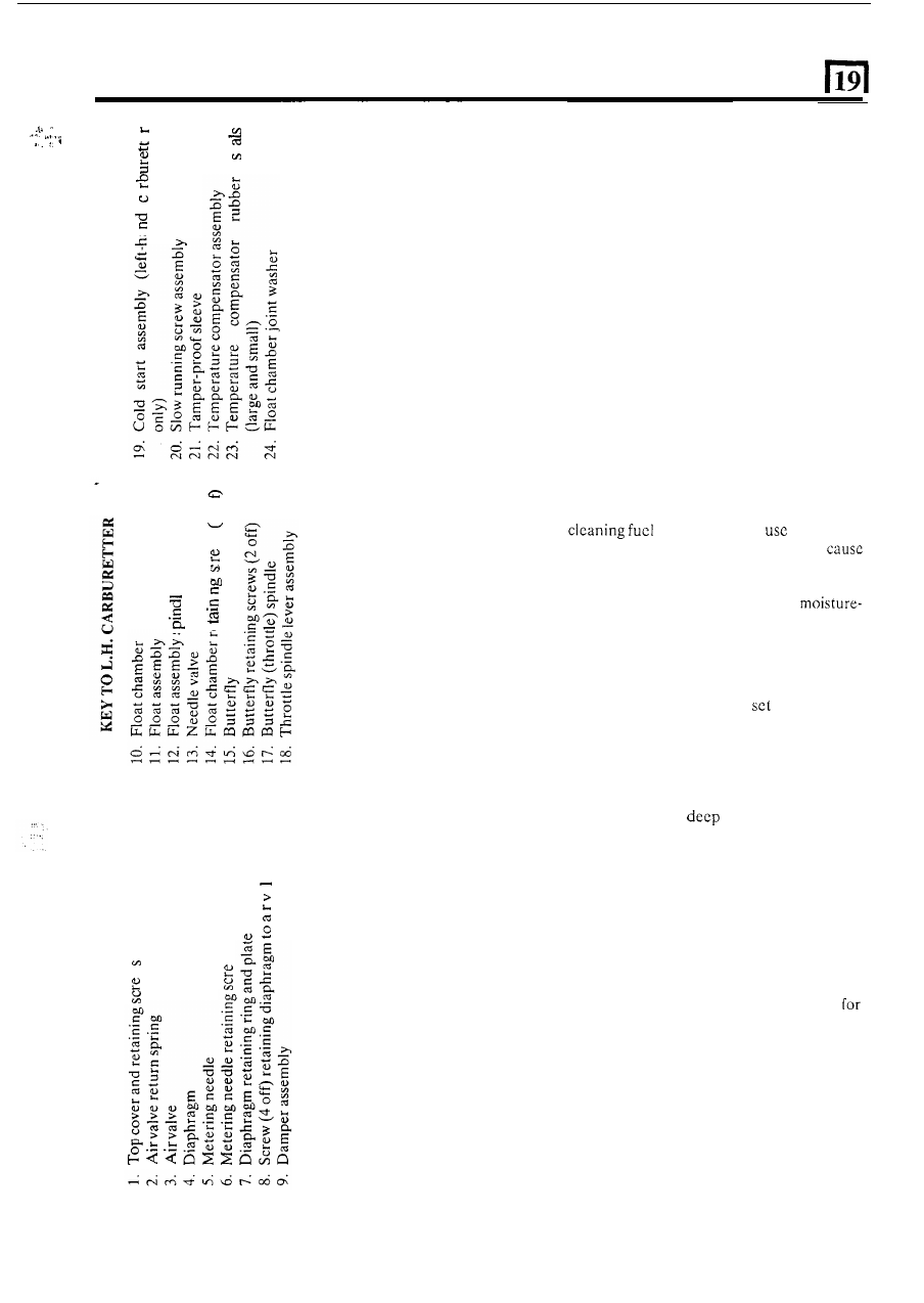
13.  Dismantle  the  cold  start  assembly  but  D O  

14. 

If  necessary,  dismantle  the  throttle  spindle  lever 

N O T  remove the discs from the spindle. 

assemblies from both carburctters. 

Slow-running adjustment screws 

D o   not  attempt  to  remove  these  screws 

or 

break  the 

tamper-proof  seals.  See  Cautionary  note  under  ‘Tune 
and Adjust’. 

Remove temperature compensator 

15.  Release  the  two  screws  and  withdraw  the 

temperature compensator 

unit complete. 

16.  Remove t h e  large and small rubber washers. 

CLEANING AND INSPECTION 

Cleaning 

17.  When 

passages d o  not 

metal tools 

(files,  scrapers,  drills  etc.)  which  could 

dimensional  changes  i n  

t h e  

drillings  or  jets. 

Cleaning 

of  all  components  should  be  effected 

using  clean  fuel  and, where  necessary,  a 
free air blast. 

.- 

VI 

Joint washers and seals 

18.  New  gaskets  and seals should  be  used  throughout 

carburetter  rebuild.  A  complete 

of  gaskets  is 

available for replacement purposes. 

Inspect  metering  needle; 

it 

is  machined  to  very 

close  limits  and  should  be  handled  with  care. 
Examine  for  wear,  bend  and  twist;  renew  if 
necessary. 

19.  Examine  the  faces 

for 

scores  which  would 

lead to leakage taking place when assembled. 

Diaphragm 

20. 

Examine  the diaphragm  for deterioration, damage 

and  punctures.  Do not  use  any cleaning chemicals 

on 

the diaphragm only clean lint free rag. 

.- 

Float assembly 

21.  Examine  the  two  plastic  floats  and  check 

22. 

Check t h e  spindle and retaining clips for wear. 

23.  Inspect the needle valve assembly for wear.  Renew 

the valve  if  there is  any tendency  for  the needle to 
stick. 

punctures and damage. 

Cold start assembly 

24.  Examine all the cold start components for wear and 

corrosion and the machined faces for scores. 

. .  

continued 

P

ETROL FUEL SYSTEM 

ASSEMBLE CARBURETTERS 

Cold start 

L.H. carburetter 

25.  Place the spring 

on the cold start spindle. 

26. 

Fit 

the spring retaining clip. 

27.  Check that 

discs slide easily on the spindle. 

Place the cold start spindle on the starter face. 

29.  Place t h e  starter cover in position. 
30. 

Fit the return spring over the spindle. 

31.  Rotate  the  spindle  until  the  oval  port  in  the 

disc is aligned with the oval port in the starter face. 

32. 

Fit 

the cold start lever. 

33.  Engage the return spring over the lug on the starter 

cover and the back 

of  t h e  cold start lever. 

body. 

34.  Place  the  cold  start  gasket  onto  the  carburetter 

35. 

Fit 

cold 

start  assembly to the carburetter body, 

Throttle spindle, R.H. carburetter 

and check for ease 

of 

operation. 

45.  Place  return  spring  over  threaded  end  of  the 

46.  Fit the throttle stop and fast idle lever. 
47. 

Fit the bushed washer, bush outwards. 

48. 

Fit the throttle lever on t h e  bushed washer. 

49. 

Fit the plain washer. 

50.  Fit the tab washer. 
5 1 .   Fit the throttle 

lever. 

52.  Secure  the  assembly  with  the  nut  and  lock  with  a 

tab. 

53.  Fit 

throttle butterfly 

as described in  instruction 

39  and  anchor  the  return  spring as illustrated. See 
note before instruction 39. 

spindle. 

continued 

Throttle spindle, L.H. carburetter 

36.  Place  the  return  spring  over  either  end 

of 

the 

spindle. 

37.  Fit  the throttle  stop and  fast  idle  lever  and  secure 

with 

tab washer and nut. 

38.  Insert 

t h e  

throttle  spindle from  the  cold  start  side 

of the  carburetter  body  and  fit  the  throttle  return 
spring on the fast  idle  adjustment lug.  Tension  the 

spring half a turn. 
NOTE:  Slacken  the  idle  adjustment screw clear  of 
lever to facilitate centralisation of the butterfly. 

39. 

Fit 

the  throttle 

butterfly,  maintaining  t h e  

previously  marked  alignment.  Leave  the  retaining 
screws loose.  Actuate  the throttle several  times 

to 

centralize  the  butterfly,  then  tighten 

t h e  

retaining 

screws and lock by peening ends. 

at 

end. 

Place 

spacer on the spindle. 

Place the tab washer o n  the spindle. 

43. 

Fit  t h e  sleeve nut, sleeve  end last, and  engage  the 

44.  Fit 

t h e  

throttle adjusting lever. 

10 

51 

tab washer. 

P

ETROL FUEL SYSTEM 

Float chamber assembly 

54.  Fit the needle valve and new washer. 

55. 

Locate  t h e   spindle 

in  the  float  arm  and  fit  the 

assembly into the retaining clips. 

seating  and 

float tab  is  contacting  the  needle. 

Measure the dimension 

between  the carburetter 

gasket face and the highest  point on  the floats. The 
correct  measurement  should  be  17 to 

18 

(0.67 

to 

0.71 in).  Adjust  by  bending  the  float  tab.  This 

dimension  must  be  the  same  for  both  floats.  The 
float carrier tab must  be maintained at right  angles 
to the needle in the closed position. 

57.  Fit  the  float  chamber  and  new  gasket  and  evenly 

tighten  the retaining screws. 

56. 

the  carburetter 

so  that  the  needle  is  on  its 

62 

Air valve and diaphragm 

58. 

Fit the diaphragm  to the air valve with the 

tag 

locating in the air valvc recess. 

59. 

Fit  the  diaphragm  retaining  ring  and  secure  with 
t h e  four screws. 

60.  Fit  the  metering  needle 

into 

air 

secure with the locking screw. 

61.  Insert the air valve  and needle into t h e  carburetter 

and  locate t h e  diaphragm  outer tag into the  recess 
in the carburetter body. 

62. 

Fit  the  spring  and  top  cover  and  secure  with  the 

four screws. 

63.  Fit the damper. 

17M 

Temperature compensator 

64.  Clean  the  carburetter  and  compensator  mating 

faces. 

65.  Fit new inner and outer rubber washer and 

the  temperature compensator with 

two  screws 

and shake-proof washers. 

Fast idle adjustment 

L.H.  carburetter only 

66.  Slacken the fast idle adjusting screw. 
67.  Hold  the  cold  start  cam  lever 

in  the  maximum 

position. 

68.  Adjust 

fast idle adjusting screw against the cam 

lever  until  there  is 

to 

(0.024  to 

0.026  in) gap  between 

t h e  

top edge of  the  throttle 

butterfly and 

t h e  

carburetter barrel wall. Use feeler 

gauges  or  a 

diameter 

(No.  72)  drill  to 

measure the gap. 

69.  Secure the  locknut on  the fast  idle  adjusting screw 

without disturbing the adjustment. 

11 

19 

PETROL FUEL SYSTEM 

ENGINE ZENITH CARBURETTERS 

TUNE AND ADJUST 

Tamper-proofing 

These  carburctters  may  be  externally  identified  by  a 
tamper-proof  sealing  tube  fitted  around  the  slow 

running adjustment screw. 

The purpose of  these carburetters is to more stringently 
control  the  air  fuel  mixture  entering  the  engine 
combustion chambers and, in consequence, the exhaust 
gas emissions leaving t h e  engine. 

For 

this  reason  the  only  readily  accessible  external 

adjustment  is  to  the  throttle  settings for  idle  and  fast 
idle  speed  and,  for  the  former  setting 

will 

require  the 

use 

of  a  special  tool  to  prevent  breaking  the  tamper- 

proof  seals. 

CAUTION:  Unauthorised  breaking of  tamper-proofing 

devices, adjustment of carburetter settings or the fitting 
of  incorrectly related  parts may render the vehicle user 
liable  to  legal  penalties  according  to  local  territory 
legislation. 
Whenever  adjustments  are  made  to  the  settings  of 
tamper-proof  or emission  specification  carburetters an 

approved type CO meter must be used to ensure that the 
final  exhaust  gas  analysis  meets  with  local  territory 
requirements. 

Emission Specifications 

All 

carburetters  fitted  to  the  Land-Rover  conform  at 

the 

time 

of 

manufacture  to  particular  territory 

requirements 

in 

respect  of  exhaust  and  evaporative 

emissions control.  However,  in  some cases changes to 
the  basic  carburetters  may  have  been  necessary  to 
achieve this. 

Service tools: 

Carburetter balancer 

Mixture adjusting tool 

MS86 

or 

Tamper-proofed 

throttle 

adjustment tool 

The  service  tool  605330  carburetter  balancer  must  be 
used  to  adjust  the  carburetters.  Primarily,  this 
instrument  is  for  balancing  the  air-flow  through  the 
carburetters,  but  it  also  gives  a  good  indication 

of 

the 

setting.  Investigation  has shown  that  incorrect 

mixture setting causes either stalling of  the engine 

or 

considerable  drop in  engine 

if  the  balancer  is 

fitted  when  the  mixture  is  too  rich  or  a  considerable 
increase 

when  used 

mixture  setting 

too  weak. 

balancing  the  carburetters  it  is  most 

important  therefore  that  the  following  procedure  be 
carried out: 

Slow running (idle) adjustment 

1.  Check  that  the  throttle  control  between  the  pedal 

and the carburetters is free and has no tendency 

to 

stick. 

2.  Check  the  throttle  cable  setting  with  the  throttle 

pedal 

in  the released position.  The throttle linkage 

must  not  have  commenced  movement,  but 

commences  with  the  minimum  depression  of  the 
pedal. 

3 .  

Run  the  engine  until  it  attains  normal  operating 
temperature; that is, thermostat open. 

4.  Remove t h e  air cleaner elbows. 
5.  Slacken  the  screws  securing  the  throttle  adjusting 

levers  on  both  carburetters  to  allow  independent 
adjustment. 

6. 

Start  the  engine  and  check  the  idle  speed  using  a 
reliable proprietary  tachometer. 
If necessary,  adjust the slow  running screw to give 
the correct idle speed, see 'Engine tuning data'. If  a 

tamper-proof  sleeve  is  fitted  over  this  screw  the 
slow  running  speed  can 

only  be  adjusted  using 

special tool MS86 or 

continued 

12 


Content   ..  52  53  54  55   ..