Defender 90 / 110 / 130. Manual - part 52


  Index      Land Rover     Defender 90 / 110 / 130 - service repair manual


Search            


Content   ..  50  51  52  53   ..


Defender 90 / 110 / 130. Manual - part 52


P

ETROL FU

EL SYSTEM 

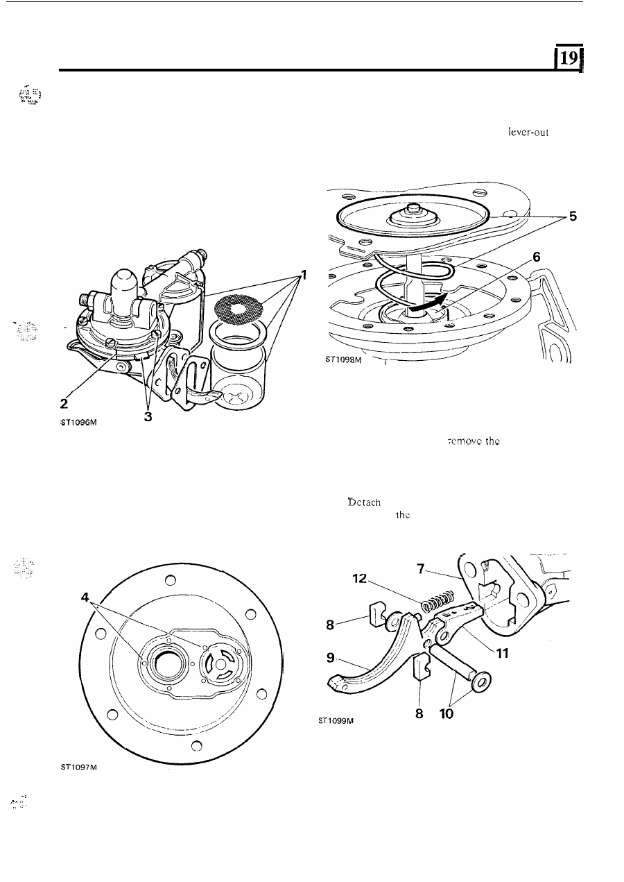
OVERHAUL FUEL LIFT PUMP 

DISMANTLE 

5 .  

Turn,  whilst  pressing  down  the  metal  part 

of  the 

diaphragm  through 

90"  in  either  direction  and 

withdraw the diaphragm and spring. 

6 .  

Unstake  the 

oil  seal  housing  and 

the  oil 

scal and retainer. 

1.  Remove  the  sediment  bowl,  where  fitted,  and 

collect the filter gauze and sealing washer. 

2.  Mark the upper and lower halves of pump casing to 

ensure correct alignment 

on reassembly. 

3.  Remove top cover fixing screws, and while pressing 

diaphragm  tab  against  pump  body,  lift  top  cover 
clear. 

7. 

Using  a  small  chisel, 

staking  from  the 

rocker arm retainers. 

8.  Withdraw the retainers. 
9.  Withdraw the rocker arm. 

10.  Withdraw the rocker arm pin and washers. 
11. 

the operating link. 

12.  Withdraw 

rocker 

arm spring. 

4. 

If  necessary  remove the valves by  cutting  away the 

retaining  stakes  with  a  scraper.  Warm  the  top 
cover, note the position 

of  the valves and withdraw 

them from the cover. 

... 

.  . 

. . . .  

.. 

13.  It is unlikely  that 

t h e  

hand  priming mechanism will 

ever require replacement, but 

i t  

can be removed by 

filing the hexagon  each  side 

of  the  operating lever 

and  springing  the  hand  lever  clear,  withdraw  the 
cork washers and hand rocker. 

PETROL 

FUEL 

SYSTEM 

14. 

16. 

17. 

18. 

19. 

20. 

Inspect 

29. 

Fit the filter gauze and sealing ring 

on 

pumps with 

sediment bowl and fit the  bowl  and secure with  the 
retaining  clip.  Ensure  that  the  bowl  and  seal  are 
located  squarely. 

Do 

not  overtighten  securing  n u t  

to prevent cracking the bowl. 

Clean 

all parts 

in 

paraffin  (Kerosene) and examine 

for  wear  and  renew  as  necessary  including  all 
gaskets 

Sediment  bowl  filter  disc  must  be  free 

of  damage 

and fit tightly around inlet neck 

of  upper casing. 

Renew  diaphragm  assembly  if  any  sign  of 

hardening, cracking 

or porosity is present. 

Only  very  slight  wear  should  be  tolerated  at  the 

rocker  arm 

face,  pivot  pin,  operating  link 

and diaphragm pull  rod slots. 
Springs  should  be  renewed  ensuring  that  the 
correct type are used. 
Test valves 

for air tightness, by suction. 

Check  upper  and  lower  casing  flanges  for 

distortion, using a straight edge. 

Test fuel pump 

Immerse  pump 

in 

a  bath  of  paraffin  and  operate 

rocker arm several times to flush. 

31.  Hold  the  pump  clear 

of  the  bath  and  continue  to 

operate  the  rocker  arm  until  the  pump  is  empty, 
then  place 

a  finger over the inlet  port  and operate 

rocker  arm  several  times. 

distinct suction  should 

be heard when  the finger is removed from  the inlet 
port,  denoting that  a reasonable  degree  of  suction 
has been developed. 

32.  Place  a  finger  over  the  outlet  port  and  again 

Assemble 

21.  Fit the rocker arm spring. 
22.  Fit 

t h e  operating link. 

23.  Fit the rocker arm pin  and washers. 
24.  Fit  the rocker  arm assembly  to the pump body  and 

secure with the retainers and stake. 

25.  Fit the 

oil seal and retainer and secure by  staking. 

operate the rocker arm. Air pressure should be felt 
for two to three seconds after rocker movement  has 
ceased.  Build  up  the  air  pressure  in  the  pump 
again,  and  with  the  finger  held  firmly  over  the 

outlet, 

the  pump  completely 

in  the 

paraffin  bath, then observe 

joint face edges for 

signs of  air leakage. 

26. 

To  refit  the  diaphragm  assembly,  hold  the  pump 
body  with  the diaphragm 

spring 

in 

position, 

and  the  rocker  arm  held  outwards.  Position  the 
diaphragm over the spring with 

t h e  

flattened end 

of 

the  pull  rod 

in  line  with  the  slot  in  the 

link. 

Push t h e  diaphragm inwards and turn to lock. 

Fit  the  inlet  and  outlet  valves  and  secure  by 

staking. 

28. 

Place  top cover  assembly 

in 

position,  aligning  the 

marks  made  before  dismantling.  Fit  securing 

screws, but  do not tighten  at this stage; using hand 
priming  lever,  fully  depress  diaphragm  and  fully 
tighten  securing screws. 
The 

diaphragm 

edges 

should 

be 

approximately  flush 

the  outer  edge 

of  the 

pump joint faces when 

OVERHAUL ELECTRICAL FUEL PUMP 

NOTE:  The  electrical  components  of  the  pump 

are 

sealed and cannot be repaired. 

DISMANTLE 

1.  Remove pump from  the vehicle,  and clean outside 

of pump before dismantling. 

2.  Release the end-cover from the bayonet fixing. 
3.  Remove the following items: 

a) 

filter and seal 

b) magnet 
c) gasket 

Pump piston assembly 

4.  Carefully prise out the retaining clip. 
5 .   The following parts will then bc released: 

a) plain  washer 
b) rubber seal 

c) one-way valve 

6. 

Withdraw t h e  piston  return  spring with  the piston. 
If  t h e   piston  remains 

in  the  pump  tube,  hold  the 

pump  body  vertically  (in  the  fitted  position)  and 
tap t h e  closed  end until  the piston  is  released  from 
its magnetic hold and drops out. 

NOTE:  The  piston  is  fitted  with  a  one-way  valve 
which should not be disturbed. 

con 

ued 

PETROL FUEL 

SYSTEM 

7.  Remove the short rebound spring. 
8.  Clean all components in paraffin. 

Immerse  pump  body 

petrol  and  use  air-line 

inside pump tube. 

la 

ST 

NOTE: The fuel  filter  assembly, instructions  2 and 
3, can be carried out with the pump on the vehicle. 

ASSEMBLE 

Pump piston assembly 

Fit the short rebound spring. 

11. 

Fit  the  return  spring over  the opposite  end  of  the 

12.  Slide the piston assembly into the pump body. 
13.  Fit the following items: 

piston. 

a) plain washer 

b) 

rubber seal 

c) one-way valve 

14. 

Secure 

t h e  

assembly 

with 

the spring clip. 

Fuel filter assembly 

Fit  the filter and seal. 

16. 

Fit the magnet. 

17.  Fit  the end cover with a new gasket. 

18.  Fit  pump  to  vehicle  and  ensure  that  the  earth 

connection lead and its mounting point is clean. 

CARBURETTER 

FOUR 

CYLINDER 

ENGINE 

OVERHAUL 

DESCRIPTION 

The twin  bored  32 

34 

DMTL Weber carburetter  is  a 

fixed  choke  instrument  with  a  staggered  throttle 
opening. The carburetter is divided, operationally, into 
two  sections  namely  the  primary  and  secondary 
carburetters with 32 

and 34 

bores respectively. 

The delayed  throttle  opening  occurs 

in  the  secondary 

carburetter. 
The primary  carburetter, which  incorporates  fuel  and 
air  jets  for  idling,  is  used  for  starting,  and  normal 
running,  up  to  approximately  two  thirds  throttle 
opening.  Shortly  before  this  stage  the  secondary 

carburetter  butterfly  will  begin 

to  open  and  become 

increasingly  more  involved  as  the  throttle  is  opened 
further.  To  ensure  a  smooth  transition  during  the 
various  stages of  throttle  opening  both  sections of  the 

carburetter  contain  progression  fuel  and  air  jets  and 

ports. 

To 

prevent fuel vaporisation and air locks 

i n  the system 

fuel  is continuously pumped  back  to the fuel  tank  from 

the 

carburetter  float  chamber.  The  top 

float 

chamber is 

so designed  that  fuel  is drawn  off  from 

main stream via  the needle valve as dictated  by  the fuel 

level 

in the chamber. 

DISMANTLE 

Remove the carburetter. 

2.  Disconnect the fast idle cam assembly. 
3.  Disconnect the 

link. 

4.  Disconnect 

pull-down  lever and linkage. 

5.  Remove the top cover from 

t h e  

carburetter body. 

6. 

Withdraw the float pivot and detach the float. 

7.  Remove the needle valve attached to the float tag. 

8. 

Remove 

discard the gasket from  the top cover. 

9.  Withdraw 

t h e  

needle valve housing. 

10.  Remove the fuel 

plug and filter. 

11.  Remove the pull-down capsule. 
12.  Remove the fuel cut-off solenoid and valve. 
13.  Withdraw  both  ‘primary’  and  ‘secondary’ idle 

holders  noting  their  positions  for  ease  of 

y. 

14.  Withdraw  both  ‘primary’ and  ‘secondary’ main  jet 

assemblies,  comprising  main  jet,  emulsion  tube 
and air correction jets. 

15.  Lift out the pump jet. 

16.  Remove  the  accelerator  pump  cover,  diaphragm, 

gasket and spring. 

Detach  the  economy  pump  assembly,  comprising 

cover, spring and diaphragm. 

18.  Remove the  idle  mixture control screw. When  the 

adjustment 

is 

tamper-proofed,  the  tamper- 

proofing cap must  be removed to expose the screw. 

continued 

ST 

535 

19-49 


Content   ..  50  51  52  53   ..