Defender (1999-2002). Manual - part 86


  Index      Land Rover     Defender - service manual 1999-2002 year


Search            


Content   ..  84  85  86  87   ..


Defender (1999-2002). Manual - part 86


60

FRONT SUSPENSION

2

REPAIR

12. Knock back staking and using a suitable socket,

remove and discard hub nut.

13. Remove washer from hub.
14. Remove hub and brake disc assembly complete

with bearings.

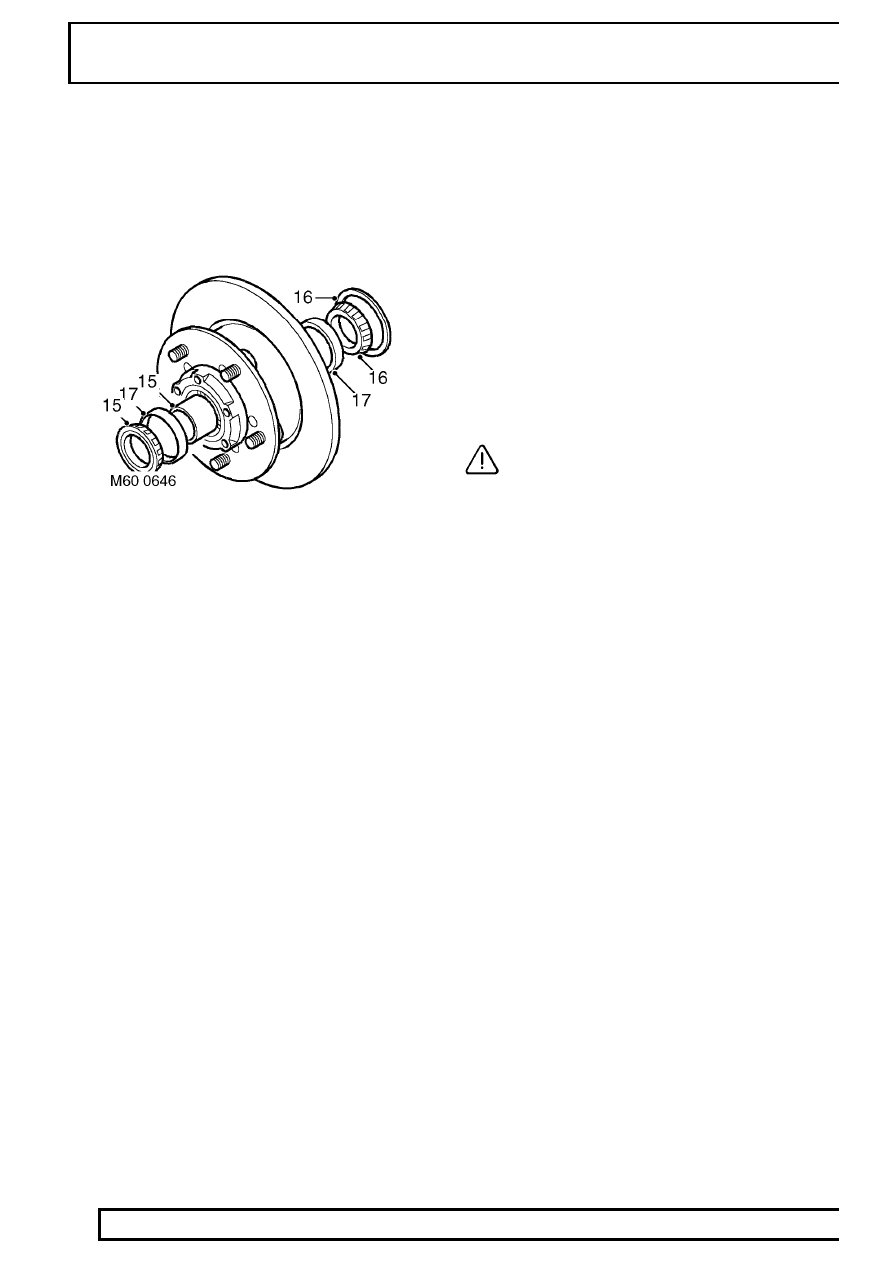
15. Remove outer bearing and spacer from hub.
16. Remove grease seal and inner bearing from

hub.

17. Remove inner and outer bearing tracks from

hub.

Refit

18. Clean hub and bearing locations.
19. Fit inner and outer bearing tracks to hub.
20. Pack inner bearing with grease and fit to hub.
21. Fit new seal flush with rear face of hub using

LRT-54-003 and LRT-99-003.

22. Clean stub axle.
23. Pack outer bearing with grease, fit spacer and

bearing to hub.

24. Position LRT-54-019 over hub nut threads on

axle casing.

25. Fit hub assembly to stub axle, remove

LRT-54-019.

26. Fit washer and new hub nut and tighten to 30

Nm (22 lbf.ft).

27. Rotate and push/pull hub to setle bearings.

Tighten hub nut to 210 Nm (150 lbf.ft).

28. To check drive shaft end float, mount a dial

gauge using bracket LRT-99-503 to driving
member bolt hole.

29. Ensure dial gauge is contacting hub nut face.
30. Move drive shaft in and out noting dial gauge

reading.

31. If end float is present refer to table for correct

spacer and change spacer as necessary.

32. When no end float is evident, remove the dial

gauge and mounting bracket.

33. Stake the hub nut.
34. Clean hub and axle shaft faces.
35. Fit new driving member gasket.
36. Position driving member to hub and tighten new

bolts to 65 Nm (48 lbf.ft).

37. Fit original shim(s) to drive shaft and secure with

circlip.

38. Position brake caliper to hub, align fixings, fit

bolts and tighten to 82 Nm (60 lbf.ft).

39. Remove plugs from brake pipe connections.
40. Connect brake pipe union to jump hose and

tighten union.

CAUTION: Use 2 spanners when
tightening or loosening unions.

41. Remove brake hose clamp from jump hose.
42. Bleed brake system. See BRAKES,

Adjustment.

43. Fit road wheel, remove axle stand and tighten

wheel nuts to 130 Nm (95 lbf.ft).

44. Operate foot brake to locate brake pads before

taking vehicle on road.

FRONT SUSPENSION

3

REPAIR

End Float (mm)

Spacer size

(mm)

Colour code

0.00

15.5

Purple

0.025

15.4

Yellow

0.050

15.4

Yellow

0.075

15.4

Yellow

0.10

15.3

Red

0.125

15.3

Red

0.150

15.3

Red

0.175

15.2

Blue

0.200

15.2

Blue

0.225

15.2

Blue

0.250

15.2

Blue

0.275

15.1

Green

0.300

15.1

Green

0.325

15.1

Green

0.350

15.1

Green

0.375

15.0

Black

0.400

15.0

Black

0.425

15.0

Black

0.450

15.0

Black

0.475

14.9

White

0.500

14.9

White

0.525

14.9

White

0.550

14.9

White

REAR SUSPENSION

1

REPAIR

BEARING - REAR HUB

Service repair no - 64.15.14

Remove

1. Raise rear of vehicle.

WARNING: Support on safety stands.

2. Remove rear road wheel.
3. Remove 2 bolts securing brake caliper to hub.
4. Release caliper from disc and tie aside.

5. Remove 5 bolts securing axle shaft.
6. Remove axle shaft and discard gasket.
7. Knock back staking, and using a suitable socket,

remove and discard stake nut.

8. Remove hub nut washer.
9. Remove hub and brake disc assembly complete

with bearings.

10. Remove outer bearing and spacer from hub.
11. Remove grease seal and inner bearing from

hub.

12. Remove inner and outer bearing tracks from

hub.

Refit

13. Clean hub and bearing locations.
14. Fit inner and outer bearing tracks to hub.
15. Pack inner bearing with grease and fit to hub.
16. Fit new grease seal flush with rear face of hub

using LRT-54-003 and LRT-99-003.

17. Clean stub axle.
18. Pack outer bearing with grease, fit spacer and

bearing to hub.

19. Fit hub assembly to stub axle, remove

LRT-54-019.

20. Fit washer and new hub nut and tighten to 30

Nm (22 lbf.ft).

21. Rotate and push/pull hub to settle bearings.

Tighten hub nut to 210 Nm (150 lbf.ft).

22. To check drive shaft end float, mount a dial

gauge using bracket LRT-99-503 to driving
member bolt hole.

23. Ensure dial gauge is contacting hub nut face.
24. Move drive shaft in and out noting dial gauge

reading.

64

REAR SUSPENSION

2

REPAIR

25. If end float is present refer to table for correct

spacer and change spacer as necessary.

26. When no end float is evident, remove the dial

gauge and mounting bracket.

27. Stake the hub nut.
28. Clean hub and axle shaft faces.
29. Fit new driving member gasket.
30. Position driving member to hub and tighten new

bolts to 65 Nm (48 lbf.ft).

31. Fit original shim(s) to drive shaft and secure with

circlip.

32. Position caliper to hub, fit bolts and tighten to 82

Nm (61 lbf.ft).

33. Fit road wheel, remove axle stands and tighten

road wheel nuts to 130 Nm (96 lbf.ft).

34. Operate brake pedal to locate brake pads before

driving vehicle.

35. Check and top up brake fluid.


Content   ..  84  85  86  87   ..