Defender (1999-2002). Manual - part 66
 

  Index      Land Rover     Defender - service manual 1999-2002 year


Search            


Content   ..  64  65  66  67   ..


Defender (1999-2002). Manual - part 66


26

COOLING SYSTEM

8

DESCRIPTION AND OPERATION

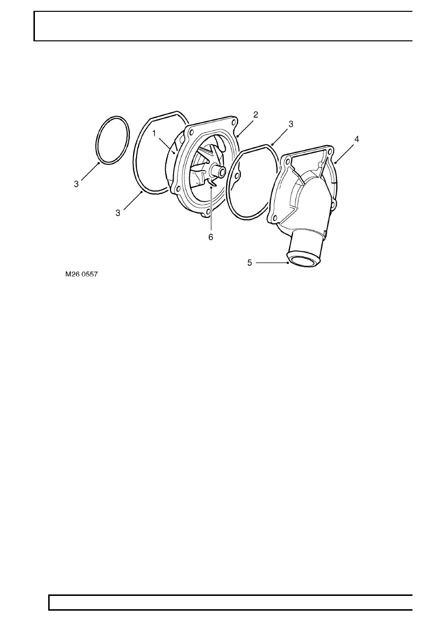
Coolant Pump

1. Drive lugs (hidden)
2. Housing
3. ’O’ rings

4. Cover
5. Feed hose connection
6. Impeller

The coolant pump is attached on the left hand side of the engine, behind the PAS pump. A cast housing, bolted to
the cylinder block provides a common attachment point for both pumps. The housing has galleries which connect
the coolant pump to the cylinder block and the oil cooler housing. The coolant pump comprises a shaft, a housing
and a cover.

The shaft, which passes through the alloy housing, is supported at each end by bearings. Seals at each end of the
shaft protect the bearings from the coolant. The forward end of the shaft has two lugs which engage with the PAS
pump shaft. The opposite end of the shaft is fitted with an impeller which draws coolant from the feed pipe and
circulates it through galleries in the cylinder block. The shaft is driven by the auxiliary drive belt at the same
rotational speed as the crankshaft by a pulley attached to the PAS pump.

The pump is sealed in the cast housing with two ’O’ rings. An outer cover is positioned over the pump and secured
with six bolts and sealed to the pump with an ’O’ ring. The cover provides the attachment for the feed pipe
connecting hose.

COOLING SYSTEM

9

DESCRIPTION AND OPERATION

Viscous Fan

1. Idler pulley drive attachment
2. Fan blades

3. Bi-metallic coil
4. Body

The viscous fan provides a means of controlling the speed of the fan relative to the operating temperature of the
engine. The fan rotation draws air through the radiator, reducing engine coolant temperatures when the vehicle is
stationary or moving slowly.

The viscous fan is attached to an idler pulley at the front of the engine which is driven at crankshaft speed by the
auxiliary drive belt. The fan is secured to the pulley by a right hand threaded nut. The nut is positively attached to
the fan spindle which is supported on bearings in the fan body. The viscous drive comprises a circular drive plate
attached to the spindle and driven from the idler pulley. The drive plate and body have interlocking annular
grooves with a small clearance which provides the drive when silicone fluid enters the fluid chamber. A bi-metallic
coil is fitted externally on the forward face of the body. The coil is connected to and operates a valve in the body.
The valve operates on a valve plate with ports that connect the reservoir to the fluid chamber. The valve plate also
has return ports which, when the valve is closed, scoop fluid from the fluid chamber and push it into the reservoir
under centrifugal force.

Silicone fluid is retained in a reservoir at the front of the body. When the engine is off and the fan is stationary, the
silicone fluid level stabilises between the reservoir and the fluid chamber. This will result in the fan operating when
the engine is started, but the drive will be removed quickly after the fan starts rotating and the fan will ’freewheel’.

26

COOLING SYSTEM

10

DESCRIPTION AND OPERATION

At low radiator temperatures, the fan operation is not required and the bi-metallic coil keeps the valve closed,
separating the silicone fluid from the drive plate. This allows the fan to ’freewheel’ reducing the load on the engine,
improving fuel consumption and reducing noise generated by the rotation of the fan.

When the radiator temperature increases, the bi-metallic coil reacts and moves the valve, allowing silicone fluid to
flow into the fluid chamber. The resistance to shear of the silicone fluid creates drag on the drive plate and
provides drive to the body and the fan blades.

COOLING SYSTEM

11

DESCRIPTION AND OPERATION

OPERATION

Coolant Flow - Engine Warm Up
During warm up the coolant pump moves fluid through the cylinder block and it emerges from the outlet housing.
From the outlet housing, the warm coolant flow is prevented from flowing through the upper and lower radiators
because both thermostats are closed. The coolant is directed into the heater circuit.

Some coolant from the by-pass pipe can pass through small sensing holes in the flow valve. The warm coolant
enters a tube in the thermostat housing and surrounds 90% of the thermostat sensitive area. Cold coolant
returning from the radiator bottom hose conducts through 10% of the thermostat sensitive area. In cold ambient
temperatures the engine temperature can be raised by up to 10

°

C (50

°

F) to compensate for the heat loss of the

10% exposure to the cold coolant return from the radiator bottom hose.

At engine speeds below 1500 rev/min, the by-pass valve is closed only allowing the small flow through the sensing
holes. As the engine speed increases above 1500 rev/min, the greater flow and pressure from pump overcomes
the light spring and opens the by-pass flow valve. The flow valve opens to meet the engine’s cooling needs at
higher engine speeds and prevents excess pressure in the cooling system. With both thermostats closed,
maximum flow is directed through the heater circuit.

The heater matrix acts as a heat exchanger reducing the coolant temperature as it passes through the matrix.
Coolant emerges from the heater matrix and flows to the fuel cooler ’T’ connection via the heater return hose.
From the fuel cooler the coolant is directed into the coolant pump feed pipe and recirculated around the heater
circuit. In this condition the cooling system is operating at maximum heater performance.

Coolant Flow - Engine Hot
As the coolant temperature increases the main thermostat opens. This allows some coolant from the outlet
housing to flow through the top hose and into the radiator to be cooled. The hot coolant flows from the left tank in
the radiator, along the tubes to the right tank. The air flowing through the fins between the tubes cools the coolant
as it passes through the radiator.

A controlled flow of the lower temperature coolant is drawn by the pump and blended with hot coolant from the
by-pass and the heater return pipes in the pump feed pipe. The pump then passes this coolant, via the cylinder
block, to the oil cooler housing, cooling the engine oil before entering the block to cool the cylinders.

When the fuel temperature increases, the heat from the fuel conducts through the fuel cooler ’T’ connection and
causes the fuel thermostat to open. Coolant from the cylinder block flows through the oil cooler and via a pipe and
hose enters the lower radiator. The lower temperature coolant from the oil cooler housing is subjected to an
additional two passes through the lower radiator to further reduce the coolant temperature. From the lower radiator
the coolant flows , via a hose, to the fuel cooler.

As the hot fuel cools, travelling slowly forwards through the cooler, it meets the progressively colder coolant
travelling in the opposite direction from the lower radiator.


Content   ..  64  65  66  67   ..