Defender (1999-2002). Manual - part 39


  Index      Land Rover     Defender - service manual 1999-2002 year


Search            


Content   ..  37  38  39  40   ..


Defender (1999-2002). Manual - part 39


ENGINE

13

OVERHAUL

Camshaft bearings - check clearance

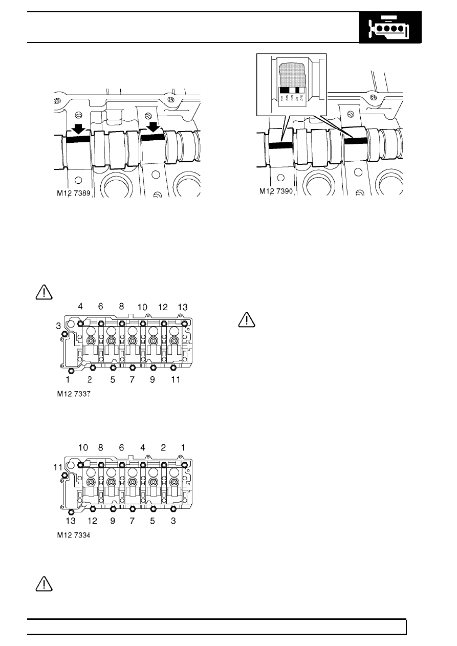
1. Position camshaft in cylinder head.
2. Place a piece of Plastigage along the centre line

of each camshaft bearing journal.

3. Carefully fit the camshaft carrier ensuring it is

located on dowels.

CAUTION: Do not rotate camshaft.

4. Fit original camshaft carrier retaining bolts and

tighten in sequence shown to 25 Nm (18 lbf.ft) .

5. Using sequence shown, loosen then remove

camshaft carrier retaining bolts.

CAUTION: Do not discard bolts at this
stage.

6. Carefully remove camshaft carrier.

7. Measure and record widest portion of Plastigage

on each camshaft bearing journal.

8. Compare figures obtained with camshaft bearing

clearance.
Camshaft bearing clearance = 0.04 to 0.10
mm (0.002 to 0.004 in).

9. If any bearing clearance is found to exceed

figures given, repeat the above procedure using
a new camshaft.

CAUTION: If, after repeating the bearing
clearance check with a new camshaft the
bearing clearances are still excessive, a

new cylinder head and camshaft carrier assembly
must be fitted.

10. Remove all traces of Plastigage using an oily

cloth, do not use a scraper.

11. Discard camshaft carrier bolts.

12

ENGINE

14

OVERHAUL

Valve springs - Inspection

1. Check free length of valve springs:

Free length =47.0

±

0.25 mm (1.85

±

0.011 in)

CAUTION: Valve springs must be replaced
as a set, if springs are to be refitted, keep
them in their fitted order.

Valves and valve guides - Inspection

1. Clean carbon from valves, check valves for

burning, pitting or cracking; replace as
necessary.

2. Clean carbon from valve seat inserts, remove all

loose particles on completion.

3. Check valve seat inserts for pitting and burning.

CAUTION: It is not permissible to recut or
replace valve seat inserts.

4. Remove carbon deposits from valve guides

using tool LRT-12-186.

CAUTION: Tool must be inserted from
combustion chamber face side of cylinder
head, ensure all loose particles of carbon

are removed on completion.

5. Check and record diameter of each valve stem.

Valve stem diameter:
Inlet = 6.907 to 6.923 mm (0.2719 to 0.2725 in)
Exhaust = 6.897 to 6.913 mm (0.2715 to 0.2721
in)

6. Renew any valve if stem diameter is less than

specified.

7. Check and record valve stem to guide clearance

using the following procedures:

8. Insert each valve into its respective guide.
9. Extend valve head 10 mm (0.375 in) out of valve

seat and position a DTI gauge to rear of valve
head.

10. Move valve towards front of cylinder head and

zero DTI gauge ensuring that stylus of gauge
remains in contact with valve head.

11. Move valve towards rear of cylinder head, record

gauge reading to give valve stem to guide
clearance.
Valve stem to guide clearance:
Inlet valve = 0.025 to 0.059 mm (0.0009 to
0.0023 in)
Exhaust valve = 0.035 to 0.069 mm (0.0013 to
0.0027 in)

CAUTION: If stem to guide clearance
exceeds figures given and valve stem
diameters were as specified, cylinder head

assembly must be replaced; it is not possible to
replace valve guides.

12. Repeat above procedures for remaining valves.

CAUTION: Keep valves in their fitted order.

13. Check face angle of each valve, renew any

valve with incorrect face angles, do not attempt
to recut.
Valve face angle:
Inlet = 
29

°

48’

±

12’

Exhaust = 44

°

48’

±

12’

ENGINE

15

OVERHAUL

Valves - Lapping-in

1. Lap each valve to its seat using grinding paste.
2. Apply Prussian Blue to valve seat, insert valve

into guide and press it firmly, without rotating on
to seat.

3. Remove valve and check that a continuous,

even line of Prussian Blue has been transferred
on to valve face.

NOTE: Line does not have to be across
whole width of valve face.

4. Remove all traces of grinding paste on

completion.

5. Check valve head stand-down. See this

Section.

Valve head stand down

1. Insert each valve into its respective guide.
2. Using a straight edge and feeler gauges, check

and record stand down of each valve head.

3. Compare figures obtained with figures given

below.
Valve head stand down:
Inlet valve = 0.555 to 0.825 mm (0.022 to
0.032 in)
Exhaust valve = 0.545 to 1.35 mm (0.021 to
0.053 in)

CAUTION: If any valve has a stand down
greater than specified, repeat check using
a new valve. If, after checking with a new

valve, stand down is still excessive, cylinder head
assembly must be replaced. It is not possible to
replace valve seat inserts.

Rocker shaft - Dismantling

1. Suitably identify each rocker arm to its fitted

position.

CAUTION: Identify type of rocker arm
fitted. Engine Serial No. Prefixes 10P to
14P - Type A rocker arms. Engine Serial

No. Prefixes 15P to 19P - Type B rocker arms.
Type B rocker arms and type B rocker shaft may
be fitted to Engine Serial No. Prefixes 10P to 14P
as an assembly.

2. Remove and discard spring ring retaining rocker

arm on shaft.

3. Remove rocker arm.
4. Remove and discard 2nd spring ring.

12

ENGINE

16

OVERHAUL

5. Repeat above procedures for remaining rocker

arms.

CAUTION: Keep rocker arms in their fitted
order.

Rocker arms and shaft - Inspection

1. Clean rocker arms and shaft, ensure oilways are

clear.

CAUTION: Identify type of rocker shaft
fitted. Engine Serial No. Prefixes 10P to
14P - Type A rocker shaft. Engine Serial

No. Prefixes 15P to 19P - Type B rocker shaft.
Type B rocker arms and shaft may be fitted to
Engine Serial No. Prefixes 10P to 14P as an
assembly.

2. Check diameter of each rocker arm journal on

shaft, take 2 measurements at 180

°

in centre of

journal.
Journal diameter = 26.971 to 26.998 mm
(1.062 to 1.063 in)

CAUTION: Any ovality must be within
limits given.


Content   ..  37  38  39  40   ..