Defender (1999-2002). Manual - part 30


  Index      Land Rover     Defender - service manual 1999-2002 year


Search            


Content   ..  28  29  30  31   ..


Defender (1999-2002). Manual - part 30


ENGINE

11

REPAIR

63. Pre EU3 model:- Fit bolt, EGR valve pipe to

cylinder head and tighten to 25 Nm (18 lbf.ft) .

64. EU3 model:- Connect coolant hoses to EGR

cooler and secure with clips.

65. Position air intake hose to EGR valve and

tighten clip screw.

66. Disconnect fuel hose from connector block and

connect to fuel cooler.

67. Connect fuel hoses to fuel cooler and connector

block on cylinder head.

68. Connect coolant hoses to fuel cooler and secure

clips.

69. Connect vacuum hose to EGR valve.
70. Position engine harness and connect multiplugs

and heater plug connectors.

71. Fit and tighten bolts, engine harness to camshaft

carrier.

72. Clean exhaust manifold and mating face.
73. Fit new gasket to exhaust manifold, position

turbocharger and tighten nuts to 30 Nm (22 lbf.
ft).

74. Clean turbocharger feed hose bolt.
75. Position feed hose using new sealing washers,

tighten bolt to 25 Nm (18 lbf.ft) .

76. Position exhaust manifold heat shield, and

tighten M6 bolts to 10 Nm (7 lbf.ft) and M8 bolt
to 25 Nm (18 lbf.ft) .

77. Position air inlet hose to turbocharger and

tighten clip screw.

78. Connect air flow meter to air filter and secure

clips.

79. Connect air flow meter multiplug.
80. Fit cooling fan. See COOLING SYSTEM,

Repair.

81. Fit camshaft cover gasket. See this Section.
82. Refill cooling system. See COOLING SYSTEM,

Adjustment.

83. Fit underbelly panel. See CHASSIS AND

BODY, Repair.

ROCKER SHAFT ASSEMBLY

Service repair no - 12.29.29

Remove

1. Remove cooling fan. See COOLING SYSTEM,

Repair.

2. Remove camshaft cover gasket. See this

Section.

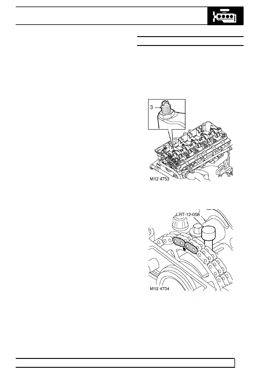
3. Loosen lock nuts and fully retract rocker

adjusting screws to prevent damage on
reassembly.

4. Rotate engine clockwise, until camshaft gear

and timing chain marks are aligned and fit
LRT-12-058 through camshaft carrier to lock
camshaft.

12

ENGINE

12

REPAIR

5. Progressively loosen then remove and discard 6

bolts; remove rocker shaft assembly.

6. Remove and discard lock nuts and rocker

adjusting screws.

Refit

7. Clean rocker shaft and mating faces.

CAUTION: If rocker arms or shaft are to be
replaced, ensure replacements are correct.
Engine Serial No. Prefixes 10P to 14P are

fitted with Type A rocker arms and shaft. Engine
Serial No. Prefixes 15P to 19P are fitted with Type
B rocker arms and shaft. Type B rocker arms and
shaft may be fitted to Engine Serial No. Prefixes
10P to 14P as an assembly.

8. Fit new rocker adjusting screws into rocker arms.

Fit new lock nuts to screws but do not tighten.

CAUTION: Ensure screws are correct for
type of rocker arm fitted. Replacement
screws for Engine Serial No. Prefixes 15P

to 19P have a centre punch mark adjacent to the
adjusting slot. These screws are not
interchangeable with those fitted to Engine Sertial
No. Prefixes 10P to 14P.

9. Fit rocker shaft ensuring it is located on dowel.

10. Fit new retaining bolts and working from the

centre outwards, tighten bolts progressively to
32 Nm (24 lbf. ft) .

ENGINE

13

REPAIR

11. Before refitting the camshaft cover, the fuel

injector rockers must be adjusted.

12. Remove LRT-12-058.
13. Rotate engine clockwise until No. 1 injector lobe

is at full lift.

14. Rotate rocker adjusting screw clockwise until the

injector plunger is felt to bottom out.

15. Rotate rocker adjusting screw anti-clockwise 1

complete turn to give the plunger the required
bump clearance and tighten rocker adjusting
screw locknut to 16 Nm (12 lbf.ft) .

CAUTION: Ensure screw does not turn as
locknut is tightened.

16. Carry out above procedure for the remaining 4

rockers.

17. After completion of rocker adjustment, slowly

rotate engine clockwise 2 complete turns by
hand to ensure that no injectors are bottoming
out on their plungers.

18. Fit camshaft cover gasket. See this Section.
19. Fit cooling fan. See COOLING SYSTEM,

Repair.

GASKET - COVER - CAMSHAFT

Service repair no - 12.29.40

Remove

1. Remove battery cover.
2. Disconnect battery negative lead.
3. Remove 3 bolts and remove engine acoustic

cover.

4. Release clip and disconnect breather hose from

camshaft cover.

5. Remove 13 bolts, spacers and sealing washers

from camshaft cover.

6. Remove camshaft cover and gasket.

Refit

7. Clean camshaft cover and mating face.
8. Renew sealing washers and spacers as

necessary.

12

ENGINE

14

REPAIR

9. Not EU3 model:- Apply two 3 mm diameter

beads of sealant, Part No.STC 5433 to areas ’A’
shown on illustration.

CAUTION: Excessive use of sealant could
result in blockage of oil drain hole,
arrowed ’B’ in illustration.

10. Fit new gasket to camshaft cover. fit cover and

tighten bolts to 10 Nm (7 lbf.ft) .

11. Position breather hose and secure clip.
12. Fit engine acoustic cover.
13. Reconnect battery negative lead.
14. Fit battery cover.

ENGINE AND ANCILLARIES

Service repair no - 12.41.01.99

Remove

1. Remove underbelly panel. See CHASSIS AND

BODY, Repair.

2. Drain engine oil.
3. Remove radiator. See COOLING SYSTEM,

Repair.

4. Remove turbocharger. See FUEL SYSTEM,

Repair.

5. Remove starter motor. See ELECTRICAL,

Repair.

6. Remove air filter. See FUEL SYSTEM, Repair.

7. Loosen clip screw and release air intake hose

from intake elbow.

8. Release clips and disconnect coolant hoses

from fuel cooler and coolant rail.


Content   ..  28  29  30  31   ..