Defender (1993+). Manual - part 107


  Index      Land Rover     Defender - service manual 1993 year


Search            


Content   ..  105  106  107  108   ..


Defender (1993+). Manual - part 107


ELECTRICAL 

EQUIPMENT 

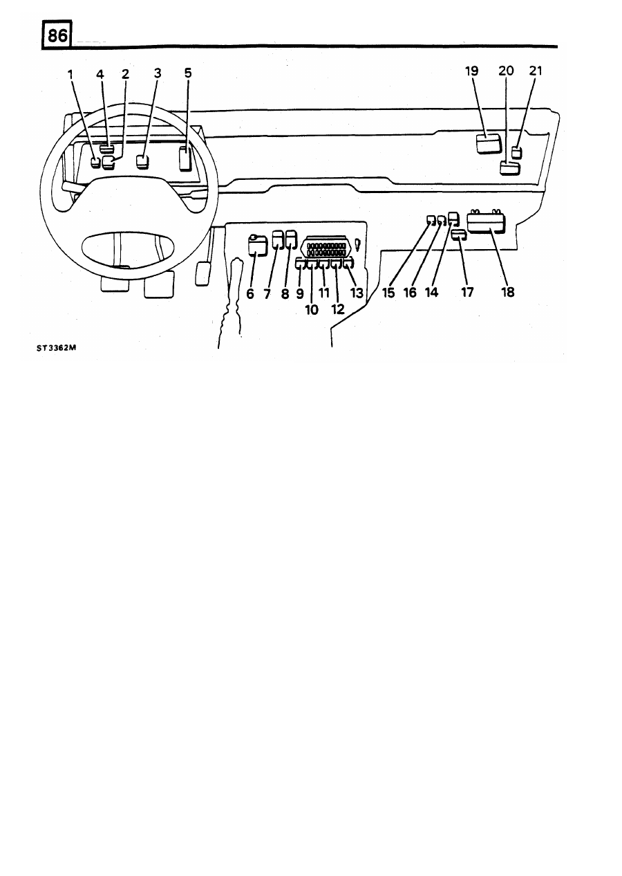
LOCATION O F  RELAYS, TIMERS AND C O N T R O L  UNITS DEFENDER 110 (ST3362M) 

Relay etc 8 circuit symbol 

Location 

Rear screen relay module HR4 

Voltage sensitive switch relay module SC2 

Water temperature signal conditioner WT2 

Service reminder unit EM1 

Inertia switch EF9 

Flasher/hazard unit DF5 

Wiper delay unit FW3 

10 

Lighting relay module LS2 

11 

Evaporator relay module AC3 

12 

Compressor relay moduler AC9 

13 

Main relay module AC1 

14 

Condenser fan timer AC7 

15 

Fuel pump relay module EF8 

17 

Diagnostic relay module MF16 

18 

MFI E C M  unit ECM 

19 

Warning buzzer unit AW6 

20 

Front screen timer HF4 

21 

Front screen relay module HF3 

Engine/brake warn light check unit WL1 

behind instrument binnacle 

Starter relay module ST6 

adjacent dash f u s e  box 

16 

Main MFI relay module EF6 

RH  toe box area 

RH upper dash area 

See  relevant  circuit  diagram 

40 

REVISED: 

OCT 

1993 

ELECTRICAL 

EQUIPMENT 

LOCATION OF RELAYS, TIMERS AND CONTROL UNITS DEFENDER 

90 

(ST3442M) 

Unit and circuit 

symbol 

Location 

Service  reminder  unit  EM1 

behind  instrument  binnacle 

Engine/brake  warn  light  check  unit  WL 


adjacent  dash  fuse  box 

Warning  buzzer  unit  AW6 

Diagnostic  relay  module  MF16 

5. 

MFI ECM unit ECM 

RH toe box area 

6. 

Main  MFI  relay module EF6 

REVISED: 

OCT 

1993 

41 

2. 

3. 

ELECTRICAL EQUIPMENT 

CIRCUIT DIAGRAMS 

The  circuits which  comprise the electrical  system  are 
presented  as  a  series 

of 

individual  circuit  diagrams 

covering a specific function, eg  starter circuit, lighting 
circuit,  audible  warning  circuit  etc.  To  ensure 
continuity 

of 

terminology  throughout  the  circuits, 

circuit  symbols and abbreviations are consistent. 

Wire 

colour  is as 

follows: 

B=black  G=green  K=pink  L=light  N=brown 
O=orange  P=purple  R=red  S=slate(grey)  U=blue 
W=white Y=yellow 

The  first  letter 

of  the  code  identifies  the  wire  main 

colour  and  the  second  letter  identifies  the  tracer 

colour. 

FUSES 

The  main  fuse  box  is  located within  the  engine bay, 
attached 

to 

the left  hand side o f   t h e  bulkhead.  The 

fuse  box  has  four fuses,  designated A,B,C  and  D for 

the  purpose 

of 

these circuit diagrams;  see  illustration 

for  details 

of 

the  fuses.  All  wires  from  the  fuse  box 

are coloured brown. 
The  auxiliary  fuse  box  is  located below the centre 

of 

the  dash.  The  fuse  box  has 

20  fuses,  designated 

to 

20; 

these  are  identified  as  F1, F2 etc  in  the circuit 

diagrams.  The  illustration  and  associated  table 

details  the  circuits  protected  by  the  different  fuses 
and the colours 

of  the wires linked 

to 

the terminals. 

In  addition  to  the  main  and  auxiliary  fuse  boxes, 

in-line fuses are protected 

in 

the following circuits: 

R1-Radio amplifier feed-5A 

C16-Air conditioning fan-30A 
R2-Radio trigger  circuit-2A 

AC 

17-Air conditioning heater relay-30A 

MAIN FUSE 

BOX SCHEMATIC 

FUSE 

ALL 

IGNITION 

FED CIRCUITS 

CIRCUITS 

OR 

DASH FUSE SERVED 

inc  dash fuses 3-4-5-16-17-18-19 

BATTERY 

FEED CIRCUITS 

inc. dash fuses 1-2-13-14-15 

DEFENDER 

90 

LIGHTING CIRCUITS 

inc. dash fuses 

6-7-8-9-10-11-12 

MFI-FUEL 

INJ. 

inc. dash fuse 

20 

4 2  

REVISED: 

OCT 

1993 

ELECTRICAL EQUIPMENT 

DASH FUSE BOX SCHEMATIC DEFENDER 

110 

ST3385M 

MAIN 

DASH 

VALUE 

CABLE 

CABLE 

CIRCUIT SERVED 

BY FUSE 

FUSE 

FUSE 

COLOUR  COLOUR 

IN 

OUT 

20A 

Aux. instrument; fog lights; horn: int. lights 

15A 

P,PW 

Hazard lights; SRI light 

15A 

Reverse light: electric screen wash 

10A 

Dimming mirror 

10A 

Stop lights, direction indicators 

7.5A 

UP 

Not used 

7.5A 

UR 

UB 

Right head lamp dipped beam 

7.5A 

UR 

UK 

Left head lamp dipped beam 

7.5A 

UW 

UO 

Right head lamp main beam 

10 

7.5A 

u w  

u s  

Left head lamp main beam 

11 

5 A 

Left side lights 

12 

5 A 

RO 

Right side lights 

13 

20A 

NP 

Heated Windshield 

14 

20A 

NO 

Air conditioning 

15 

5 A 

NS 

Air conditioning 

16 

5 A 

Rear screen wash/wipe 

17 

10A 

WB 

NW 

Heated rear window 

18 

10A 

Cigar lighter 

19 

WO 

w o  

Radio 


20 

7.5A 

WP 

WU 

Fuel pump 

REVISED: OCT 

1993 

43 


Content   ..  105  106  107  108   ..