Defender (1993+). Manual - part 102


  Index      Land Rover     Defender - service manual 1993 year


Search            


Content   ..  100  101  102  103   ..


Defender (1993+). Manual - part 102


ELECTRICAL EQUIPMENT 

RENEW 

WIPER 

MOTOR 

AND DRIVE RACK 

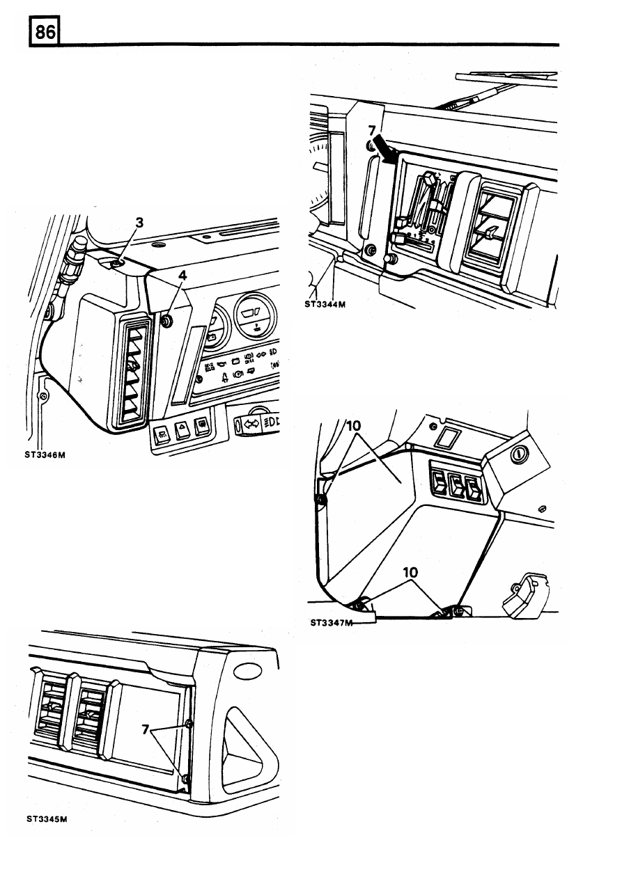
Removing wiper motor 

1. 

Disconnect the battery. 

2. 

Remove the wiper  arms. 

3. 

Remove  the  single  screw  and  remove  the 

fascia side panel. 

4. 

Remove  the  five  screws  and  withdraw  the 
instrument  panel  as  far  as  possible  without 

straining the wires  and cables. 

8. 

Release  the  fascia  panel  left-hand  support 
bracket. 

9.  Remove fascia lower  panel finisher. 

10. 

Remove fascia lower  panel. 

5. 

Remove  the  single  screw  securing  steering 

wheel centre pad. 

6.  Turn  steering  wheel  to  straight ahead position 

and  mark  the  relationship 

of 

the  steering 

wheel  to  the  column  and  remove  the  nut. 
Withdraw  the  wheel  using  special 

tool 

18G 

1014 

or  a suitable alternative puller. 

7 .  

To 

remove  the  air  conditioning  panel  and 

controls,  remove  the 

two 

screws  at  the  right 

hand side of  the panel and the single screw at 
the left-hand side,  inside the instrument cowl. 

20 

REISSUED: 

FEB 

1993 

ELECTRICAL EQUIPMENT 

11. 
12. 

Remove earth lead. 

13.  Lift  rubber  sleeve  from  wiper  motor  and 

Remove 

slacken wiper  motor to drive tube  nut. 

14.  Remove  the  wiper  motor  retaining  strap 

1. 

Pull the wiper  arm away  from  the windscreen. 

screws  and  remove  strap  together  with 

2.  Using  a  small  screwdriver,  hold  back  the 

mounting pad and earth tag. 

spring  clip  which  retains  the  arm  to  the 

15.  Pull  the  wiper  motor  and  drive  rack  clear  of 

the drive  tubes. 

Disconnect the wiper  motor wiring  multiplug. 

RENEW  WINDSCREEN  WIPER  ARMS 

spindle adaptor. 

3. 

Pull the wiper  arm from the splined adaptor. 

4.  Switch  the  wiper  motor  to  the  "park"  position 

with  the  grub  screw,  retaining  the  adaptor, 
uppermost. 

5.  Push  the  arm 

on 

to  the  adaptor 

so 

that  the 

wiper  blade  is  just  clear 

of  the  windscreen 

surround rubber. 

6.  Operate  the  wipers  and  if  necessary  adjust 

the position of  the arms. 

Fitting 

wiper  motor 

16.  Feed  the  drive  rack  into  the  drive  tube  until 

fully located in the wheel boxes. 

17. 

Finger tighten the drive tube nut. 

18.  Position  the  motor  mounting  pad  and  secure 

the  assembly  with  the  strap 

and 

screws  not 

forgetting the earth tag. 

19. 

Tighten  the  drive  tube  nut  and  position  the 
rubber sleeve over the nut. 

20.  Connect  the  multiplug  to  the  motor  and  the 

earth lead to the tag on motor  retaining strap. 

21.  Before  fitting  the  fascia  panels,  fit  the  wiper 

blades, connect  the  battery  and test  the  wiper 
operation. 

22.  Refit  the  fascia  panels  noting  that  the  air 

conditioning  panel  must  be  located  and 

secured,  on  the  left  side,  with  the  single 
screw, before the  instrument panel is fitted. 

23.  Fit the  steering wheel ensuring that  the  marks 

made during removal coincide. Fit  and tighten 

the securing nut to the correct torque. 

24.  Fit  the  steering  wheel  centre  pad  with  the 

single screw. 

REISSUED: 

FEB 

1993 

21 

ELECTRICAL EQUIPMENT 

RENEW WINDSCREEN WIPER  WHEELBOXES 

Remove 

7.  Remove demister vent top duct. 

6. 

Remove  right-hand  vent  demister  vent  fixing 

and pivot vent  and hose aside. 

8. 

Release the  steering column  upper  and  lower 

9.  Slacken  the  left  and  right-hand wheelbox  nuts 

1. 

Disconnect the battery. 

support  rods. 

2.  Carry-out the  instructions to  remove the  wiper 

motor  and  drive  rack  for  air  conditioned 

and remove drive tubes from  wheelboxes. 

vehicles, that  is: 

10.  Remove wiper  arm splined adaptor. 

Wiper arms 

11.  Remove  spacer,  where  fitted,  early  vehicles 

Fascia side panel 

only. 

Instrument housing 

12.  Remove  nuts  securing  left  and  right-hand 

Fascia top crash rail 

wheel  boxes  and  withdraw  wheelboxes  from 

Steering wheel 

bulkhead. 

Fascia panel air  conditioning controls 

Fitting wheelboxes 

NOTE:  It  is  important  that  during  the  following 
assembly  the  fixings  related  to  the  wiper  motor 
and wheelboxes are finger tightened only  until all 

Wiper  motor and drive rack 

3.  Remove centre and  left-hand fascia top crash 

rail support bracket fixings. 

4. 

Remove  left  and  right-hand  demister  vents 

the components are correctly aligned. 

from  ducts. 

5.  Remove  right-hand  demister  vent  hose  from 

duct. 

22 

REISSUED: FEB 1993 

ELECTRICAL 

EQUIPMENT 

13.  Fit  the  wheelboxes  to  the  bulkhead  and 

ELECTRICAL 

SYSTEMS 

loosely secure with the nut  and washer. 

14. 

Loosely fit the  drive tubes to  the wheelboxes 

The electrical  systems on  the  vehicle  are  made 

up of 

15. 

Feed  the  drive  rack  through  the  tubes  until 

separate  harnesses  of  which  the  Engine  Harness, 

fully  seated in both wheelboxes. 

Chassis  Harness  and  Main  Harness  Assembly  are 

16. 

Loosely secure drive  tube nut to  wiper 

motor. 

the  main  components.  These  three  harnesses 

17 

Loosely 

fit 

the  wiper  motor  strap  and  earth 

connect 

together 

and 

to 

smaller 

individual 

lead. 

component  harnesses  to  form  the  vehicle  harness. 

18. 

When  all  components  are  correctly  aligned, 

Each  harness  can  be  separated  and  replaced 

tighten  the  wheelbox  nuts  to  secure  the  drive 

individually  The  harnesses  are  shown  in  situ  in  the 

tubes.  Tighten the wheelbox  to  bulkhead nuts. 

vehicle. 

19. 

Finally  tighten  the  dnve  tube  nut  to  wiper 

motor and motor  strap screws. 

The  following  harness descriptions include  listings of 

20.  Connect  the  multiplug  to  wiper  motor  and 

the  items  connected  onto  each  harness  and  the 

earth lead to  strap tag. 

colour  coding  of  the  relevant cables  For  information 

21.  Fit  the  spacer,  where  used,  early  vehicles 

on  the  individual  circuits  which  form  the  vehicle 

only. 

electrical system, refer to  the  Circuit  Diagrams. 

22.  Fit the wiper  arm  adaptors. 
23.  Connect  the  battery  and  check  the  operation 

For  information 

on 

the  location  and  identification of 

of  the  motor  and  drive  assembly  and 

relays. timers  and control  units, refer to  the  table and 

wheelboxes. 

illustration in this section. 

24.  Disconnect 

the 

battery 

and 

reverse 

instructions  2  to  10.  Ensure  that  the  steering 
column  upper  and  lower  support  rod  fixings 
are tightened 

to 

the  correct torque. 

25.  Reconnect  the  battery  and  check  wiper 

operation again and adjust arms if necessary. 

23 

RE-ISSUED: 

FEB 

1993 


Content   ..  100  101  102  103   ..