Defender (1993+). Manual - part 63
REAR AXLE
AND FINAL DRIVE
109.
Prevent the drive pinion from rotating and
check the crown wheel backlash
which
must
be 0,15 to 0,27 mm. If the backlash
is
not
within the
specified limits, repeat the
differential backlash checks, instructions 96 to
102 looking for possible errors.
110.
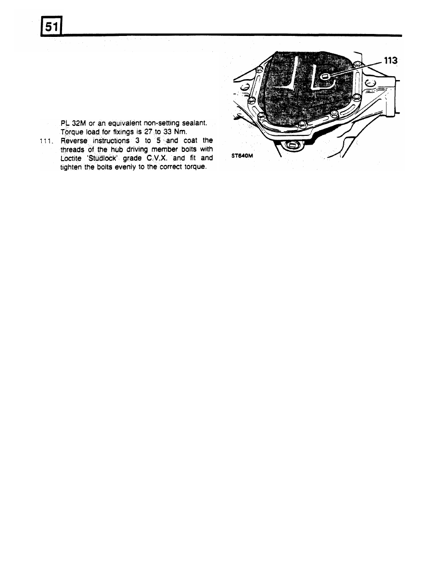
Fit
the differential cover and new gasket,
coating both sides of the gasket with Hylomar
112. Fit the rear axle assembly to the vehicle.
113. Replenish the differential lubricating oil, (see
114. Where major running parts have been
Lubrication chart). After the initial axle run,
replaced
during
servicing,
it
is
a
check the
oil
level and replenish as necessary
recommended practice to allow the axle
to
the filler/level plug hole.
assembly
to
'run in' by avoiding, where
possible, heavy loads and high speeds during
initial running.
DATA
Crown wheel backlash
...........................................................
0,15 to 0,27 mm
Differential bearings pre-load
.................................................
0,127 mm
Pinion height setting
...............................................................
Set using gauge 18G 191 P or 18G
191 -4
Torque resistance initial setting figures
Torque to
turn
drive pinion and new pinion bearings
Torque to
turn
drive pinion re-using the original bearings
OVERHAUL REAR AXLE DIFFERENTIAL
ASSEMBLY DEFENDER
90
The differential fitted to the rear axle on Defender 90
vehicles is identical to the differential fitted to the
front axle. For overhaul instructions refer to Section
54.
34,5 to 46 kgf cm
17,3
to
34,5
kgf cm