Defender (1993+). Manual - part 24
 

  Index      Land Rover     Defender - service manual 1993 year


Search            


Content   ..  22  23  24  25   ..


Defender (1993+). Manual - part 24


ST841M 

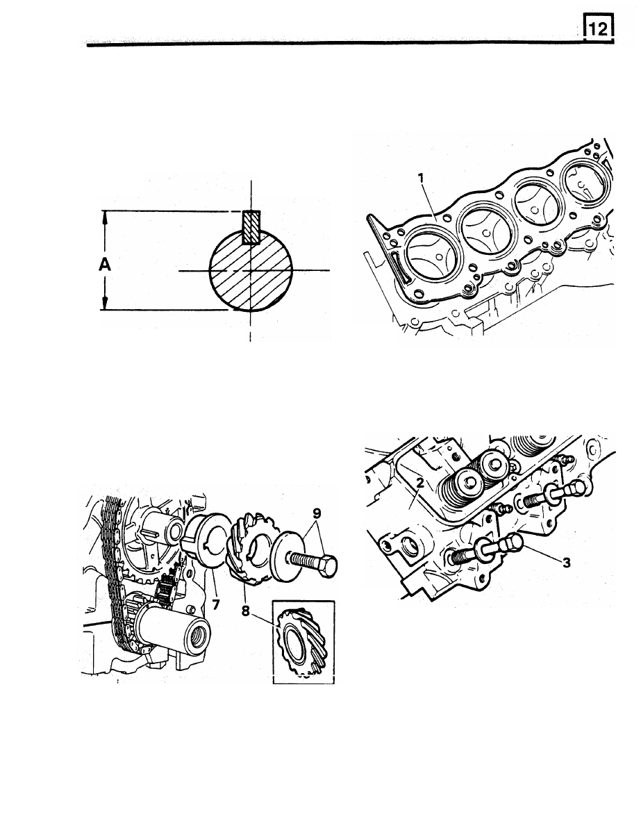
CAUTION:  The  space  between  key  and 

FIT CYLINDER HEADS 

keyway acts as an oilway  for  lubrication 

of 

drive gear.  Ensure that  key is seated to 

full 

depth  of  keyway.  Overall  dimension 

of 

uppermost. 

Do 

NOT use sealant. 

shaft  and  key  must 

not 

exceed 

30.15 

mm, 

dimension A  below. 

1. 

Fit new cylinder head gaskets with word 

'TOP' 

ST843M 

2. 

Locate cylinder heads on dowels. 

3.  Clean  threads  of  cylinder  head  bolts  and 

lubricate with engine 

oil. 

7. 

Check  timing  marks  line  up, 

fit 

spacer  with 

flange 

to 

front. 

8. 

Fit  the  distributor  drive  gear.  Ensure  that 

annular  grooved side  is 

fitted 

to 

rear, towards 

spacer. 

9.  Fit  bolt  and  washer,  tighten  to  correct  torque, 

60 

Nm. 

RR755M 

4. 

Locate  the  cylinder  head  bolts  in  position 
illustrated and 

fit 

dipstick tube. 

Long bolts 

1, 

and 5. 

Medium 

bolts 

2,4,6,7,8,9  and 10. 

Short  bolts 

11,12,13 and 14. 

RR1799E 

ENGINE 

ENGINE 

5. 

Tighten  head  bolts  progressively  in sequence 
shown.  Finally  tighten 

to 

correct  torque,  outer 

row 

60 

Nm centre and inner row 

90 

Nm. 

tightened. 

3. 

Ensure  each  rocker  shaft 

I

fitted  with  notch 

uppermost  and  towards  front  of  engine  on 
right  hand  side,  towards  rear  on  left  hand 

6. 

Re-check  torques  when  all  bolts  have  been 

side. 

ST845M 

NOTE:  Left-hand cylinder  head  illustrated. 
Arrow points to front of vehicle. 

RR2241E 

FIT  TAPPETS,  PUSH  RODS  AND  ROCKER 

4. 

Fit  rocker  shaft  assemblies.  Ensure  pushrods 

ASSEMBLIES 

engage  rocker  cups.  Tighten  bolts 

to 

correct 

torque, 38 Nm. 

NOTE:  Immerse  tappets 

in 

clean  engine  oil. 

Before  fitting,  pump  inner  sleeve 

of  tappet 

several times  using a  pushrod, to  reduce tappet 
noise when engine i s  started. 

1. 

Fit tappets and push rods in original positions. 
Ensure tappets move freely 

in bores. 

NOTE:  Tappet  noise  can 

be  expected  on 

initial  starting  after  overhaul  or  if  vehicle 
has been standing a very long period. Run 

engine  at 

2,500 

rev/min for  a  few  minutes 

(subject  to following  caution),  when  noise 
should 

be 

eliminated. 

2.  Rocker  shafts  are  handed  and  must  be  fitted 

correctly 

to 

align oilways. 

CAUTION: 

Do  not  exceed 

1,000 

engine 

rev/min for 

15 

seconds when  first  starting 

engine,  otherwise  crankshaft  rear  oil  seal 
will 

be damaged. 

8. 

Fit  all  manifold  bolts,  evenly  tighten  a  little 

at 

a time,  alternate  sides  working 

from 

centre 

to 

each  end.  Finally tighten to  correct  torque, 

40 

9. 

Tighten  gasket  clamp  bolts 

to 

correct  torque, 

FIT INTAKE MANIFOLD 

1. 

Apply  globule  of  Hylomar  SQ32M  sealing 

Nm. 

compound  to  notches  between cylinder  head 
and block. 

18 Nm. 

2.  Locate 

NEW  seals 

in  position  with  ends 

engaged in notches. 

RR2268E 

FIT TIMING COVER  AND  CRANKSHAFT PULLEY 

3. 

Apply  'Hylomar' SQ32M on corners of  cylinder 
head,  manifold  gasket  and  manifold,  around 
water  passage joints. 

4. 

Fit manifold gasket with word 'FRONT'  to front 
and open bolt hole at front 

R.H. side. 

5. 

Fit gasket clamps, do not fully  tighten bolts. 

1. 

Position  a  new  timing  cover  joint  washer,  fit 

timing cover, locating 

it 

on 

two dowels. 

2.  Clean  threads  of  timing  cover  securing  bolts, 

coat them with  Loctite 572. 

3. 

Fit  and  evenly  tighten  timing  cover  bolts  to 

correct torque, 28  Nm. 

4. 

Fit  crankshaft  pulley. Tighten  retaining  bolt  to 
correct torque, 270 Nm. 

5.  Fit timing pointer. 

6. 

Locate manifold on to cylinder head. 

7. 

Clean threads of  manifold securing 

bolts. 

ENGINE 

ST849M 

ENGINE 

RR1795E 

FIT WATER  PUMP 

TEST 

AND 

FIT 

THERMOSTAT 

1. 

Lightly grease  a new joint  washer and place 

it 

in position on timing cover. 

1. 

Remove 

two 

bolts  securing  thermostat 

2.  Clean threads of  four  long bolts and coat  with 

Loctite 

572 

thread lubricant sealant. 

2.  Remove housing gasket. 

Locate water  pump in position. 

3. 

Withdraw thermostat. 

3. 

Locate  alternator  adjusting  link  on  water 

pump. 

4. 

Leaving alternator  adjusting  link  loose,  tighten 

remaining water  pump  housing bolts evenly 

to 

correct torque 

28 

Nm. 

housing to  intake manifold. 

RR1791E 

4.  Note  fully  open  temperature  stamped  on 

thermostat, 

88°C. 

FIT 

SUMP 

1. 

Remove  old  sealant  from  sump  and  cylinder 

block joint  faces. 

face of  sump as 

shown 

in 

illustration below. 

2.  Apply  2  mm  wide  bead of  Hylosil 102 to joint 

RR799M 

5.  Place  thermostat  and  a  thermometer  in  a 

suitable container half 

full 

of 

water. 

RR1867E 

3. 

Place sump  in position, 

fit 

sump  bolts,  evenly 

tighten  bolts  to  correct  torque, 

10 

Nm,  rear 

bolts 

19 

Nm. 

4. 

Tighten sump plug 

to 

correct torque, 44Nm. 

5.  Allow  thirty  minutes sealant curing time before 

starting engine. 

ST858M 


Content   ..  22  23  24  25   ..