Defender Electric Diagrams. Manual - part 104
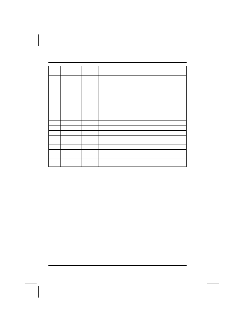
FUSE DETAILS
2.4
DEFENDER 1999 MY
Fuse
Rating
Wire
colour
Function
11
10 Amp
RB/R
Lighting switch, LH front side lamp, LH tail lamp,
trailer pick-up.
12
10 Amp
RO
Lighting switch, RH front side lamp, RH tail lamp,
cigar lighter, dim-dip relay, headlamp levelling
switch, coolant temperature gauge sensor, fuel
gauge, LH heater control illumination, RH heater
control illumination, clock illumination, instrument
pack, blower motor switch, RH headlamp levelling
motor, LH headlamp levelling motor, aircon switch
pack.
13
20 Amp
PG
Cigar lighter, blower motor.
14
5 Amp
WO
Radio/Cassette player.
15
10 Amp
UB/UR
Dim-Dip relay, RH headlamp.
16
10 Amp
UK/UR
Dim-Dip relay, LH headlamp.
17
10 Amp
UO/U-
W
RH headlamp, instrument pack, column switch.
18
10 Amp
US/UW LH headlamp, instrument pack, column switch.
19
10 Amp
U/UP
Rear fog lamp ECU, column switch, headlamp
relay, dim-dip relay.
20
10 Amp
OR/PB
Alarm sounder relay, horn switch, LH horn, RH
horn.