Defender. Manual - part 251


  Index      Land Rover     Land Rover Defender - service manual 2007 year


Search            


Content   ..  249  250  251  252   ..


Defender. Manual - part 251


3. With assistance, lift rollover bar assembly and position on

fenders.

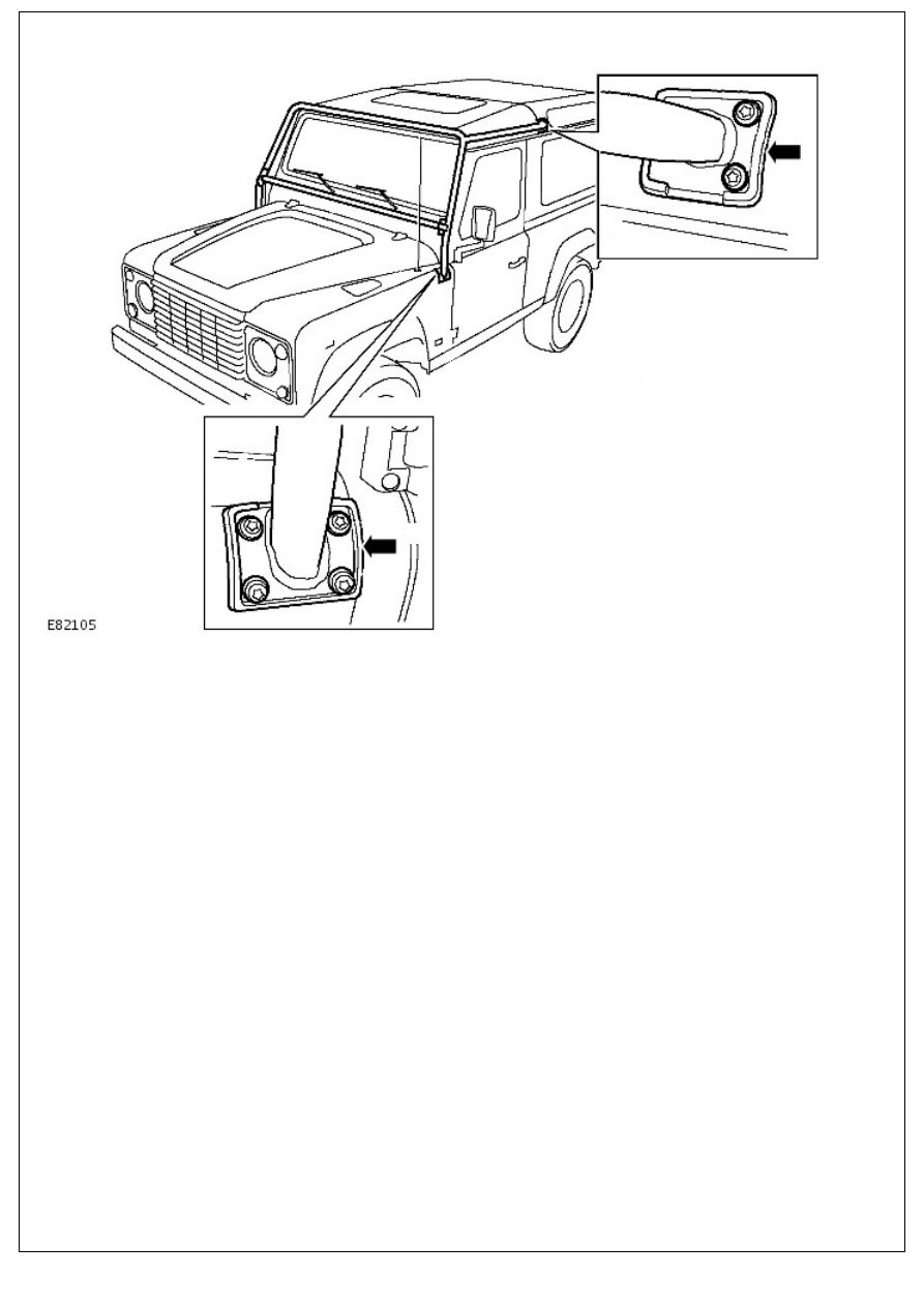
4. Slide top bars into main rollover bar, position on roof

mounting and secure withTorx bolts to 25 Nm (18 lbf ft.).

5. Secure rollover bar to both fender mountings with Torx

bolts. Tighten to 25 Nm (18 lbf.ft).

6. Secure top bars to main rollover bar and tighten fixing bolts

to 25 Nm (18 lbf.ft).

Exterior Trim and Ornamentation - Radiator Grille

Removal and Installation

Removal

1. Disconnect the battery ground cable. 

For additional information, refer to: 

Battery Disconnect and

Connect

 (414-01 Battery, Mounting and Cables, General

Procedures).

2. Remove the radiator grille.

Remove the 6 screws.

Installation

1. To install, reverse the removal procedure.
2. Connect the battery ground cable. 

For additional information, refer to: 

Battery Connect

 (414-01

Battery, Mounting and Cables, General Procedures).

Exterior Trim and Ornamentation - Rear Folding Step

Removal and Installation

Removal

1. Remove 2 bolts securing step to chassis member, remove

step and collect spacers.

Installation

1. Position step, fit spacer washers and tighten bolts.

Exterior Trim and Ornamentation - Towbar

Removal and Installation

Removal

1. Remove 4 bolts securing stabilizer bar to rear undershield.
2. Remove 6 bolts securing rear undershield to chassis.
3. Remove rear undershield.
4. Remove bolt, washer and nut from both sides, securing tow

bar lower mounting brackets and towing eyes to chassis.

5. Remove 4 bolts and spring washers securing tow bar centre

mounting bracket to chassis.

6. Remove both bolts securing 2 tow bar locating tubes in

chassis rear cross member.

7. Remove 2 bolts securing tow bar top mounting brackets to

chassis.

8. With assistance, withdraw tow bar assembly from chassis.

Installation

1. With assistance, lift tow bar assembly and locate both tubes

in chassis crossmember.

2. Secure top tow bar mounting brackets to chassis but do not

fully tighten fixings.

3. Secure tow bar locating tubes to rear of chassis and tighten

bolts to 25 Nm (18 lbf.ft).

4. Secure tow bar centre mounting bracket to underside of

chassis and tighten bolts to 25 Nm (18 lbf.ft).

5. Position towing eyes to lower mounting brackets and secure

to chassis and tighten bolts to 25 Nm (18 lbf.ft).

6. Fully tighten tow bar top mounting bracket bolts to 25 Nm

(18 lbf.ft).

7. Fit rear undershield and secure to chassis with bolts.
8. Fit bolts securing rear stabilizer bar and tighten to 30 Nm

(22 lbf.ft).


Content   ..  249  250  251  252   ..