Defender. Manual - part 237
12
-
Map reading lamp (SVX (60th anniversary) model only)
OVERVIEW
Each interior lamp contains a 3 way switch, allowing always on, always off, or automatic operation. When in the always
on position, the interior lamp is provided with a battery voltage feed from the CJB. When in the automatic position,
operation of the interior lamps is controlled by the anti-theft system module. The anti-theft system module monitors the
condition of the doors, including the tail door, through a series of switches. If any of the doors are opened a ground
path is created through the relevant switch. When the anti-theft system module registers a ground path it illuminates
the interior lamps. If the door(s) are subsequently closed, the anti-theft system module will extinguish the interior lamps
after a period of 15 seconds.
The anti-theft system module will also illuminate the interior lamps if it receives a valid unlock signal from the remote
radio frequency (RF) handset.
For additional information, refer to:
Anti-Theft - Active
(419-01A Anti-Theft - Active, Description and Operation).
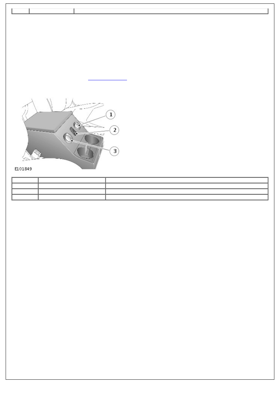
SVX (60th Anniversary) Model
Item
Part Number
Description
1
-
LH map reading lamp
2
-
Map reading lamps control switch
3
-
RH map reading lamp
The SVX model has all the interior lighting features of the standard models but with the addition of 2 map reading
lamps.
The map reading lamps are located on the forward face of the cubby box with a control switch positioned between them.
The lamps use a W3W bulb. The bulb can be replaced by carefully levering the lamp from the cubby box using a suitable
tool and removing the bulb holder from the rear of the lamp.
The map reading lamps are connected directly to the vehicle battery via fuses in the CJB and the battery junction box
(BJB). Therefore the map reading lamps can be operated independent of the ignition switch position. Each lamp receives
a battery voltage supply and the lamp illuminates when the switch is operated which completes a ground path.
CONTROL DIAGRAM
• NOTE: A = Hardwired