Defender. Manual - part 220


  Index      Land Rover     Land Rover Defender - service manual 2007 year


Search            


Content   ..  218  219  220  221   ..


Defender. Manual - part 220


Battery, Mounting and Cables - Battery and Cables

Description and Operation

COMPONENT LOCATION

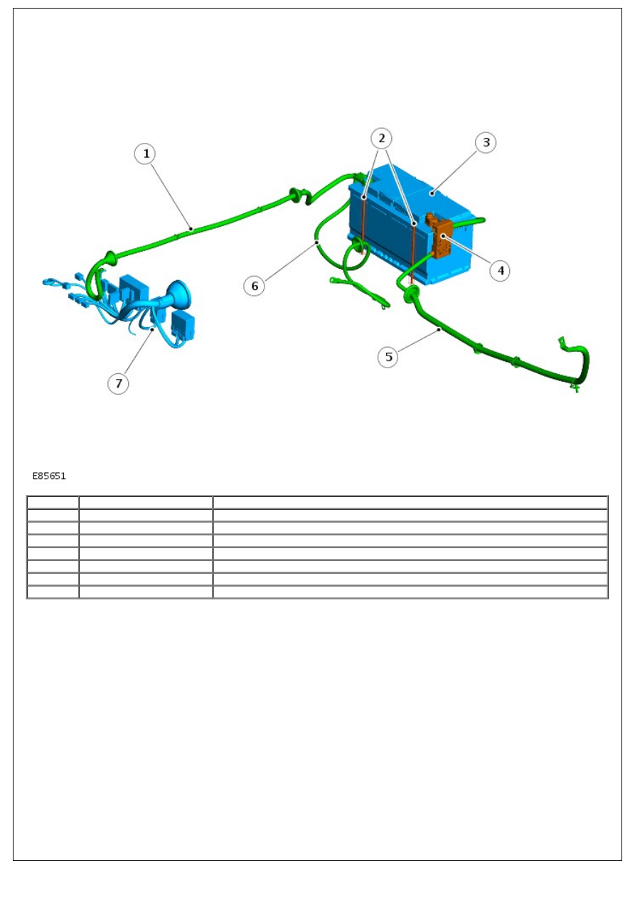
Battery Junction Box

Item

Part Number

Description

1

-

Power feed to battery junction box (BJB)

2

-

Battery clamps

3

-

Battery

4

-

Mega fuse

5

-

+VE battery cable

6

-

-VE battery cable

7

-

BJB

OVERVIEW

The battery is mounted in a protective box, located under the LH seat. It sits in a tray and is secured with clamp plates

and bolts.

The battery terminal posts allow for the battery cables to be connected with clamp type connections.

The battery positive terminal is fitted with a mega fuse, which is a 500 Amp device housed in a black fuse carrier,

integral to the battery clamp. Power feed to the BJB is taken from a tap on the battery clamp before the mega fuse.

In the event of a crash the mega fuse is designed to blow, this isolates the power from the generator and starter motor,

but allows power to be delivered, via the central junction box (CJB), to the rest of the vehicle.

The battery is a .

The battery is a H8, semi-sealed type. Each casing has a vent to allow for thermal expansion and to vent oxygen and

hydrogen gases, which are produced under certain charging conditions.

When removing the battery, ensure the alarm is disarmed and the ignition is switched off. Always disconnect the

negative terminal first and then the positive. When refitting the battery, always fit the positive terminal first followed by

the negative.

If the battery requires recharging, always use an approved constant current charger, designed for lead-calcium

batteries. DO NOT use a fast charger, as permanent damage to the battery may occur.

Starter Fuse

Incorporated in the cable between the battery and the starter motor/generator is a 500A mega fuse. The fuse is

mounted adjacent the battery positive terminal and is integral with the cable assembly. In the event of fuse failure, the

complete cable assembly must be replaced.

CENTRAL JUNCTION BOX

• NOTE: LH drive shown .

CJB Relay Descriptions

Location

Description

1

Headlamp relay

2

Heated rear window relay

3

Wipers relay

4

Electric window lift relay

5

Indicator flasher relay

6

Alarm relay

CJB Fuse Descriptions

Name

Item Number

Rating (Amps)

Fuse color

Circuits protected

F8

16

10

Red

Alarm system

F9

15

15

Blue

Front wipers/wash

F10

14

10

Red

Rear wipers/wash

F11

13

10

Red

Anti-lock brakes

F12

12

10

Red

Speed transducer

F13

11

10

Red

Brake lamps

F14

10

10

Red

Reverse lamps

F15

9

5

Tan

Ignition

F16

8

-

-

Not used

F17

7

-

-

Not used

F18

17

10

Red

Side lamps (left)

F19

18

10

Red

Side lamps (right)

F20

19

10

Red

Illumination/clock illumination

F21

20

10

Red

Hazard switch

F22

21

10

Red

Headlamp dipped beam (right)

F23

22

10

Red

Headlamp dipped beam (left)

F24

23

10

Red

Headlamp main beam (right)

F25

24

10

Red

Headlamp main beam (left)

F26

25

10

Red

Rear fog lamps

F27

26

10

Red

Alarm sounder

F28

36

20

Yellow

Heated rear window

F29

35

20

Yellow

Cooling fan/A/C clutch link

F30

34

10

Red

Audio/clock/diagnostic socket

F31

33

15

Blue

Hazard switch

F32

32

-

-

Not used

F33

31

20

Yellow

Seat heater

F34

30

20

Yellow

Electric window (right)

F35

29

20

Yellow

Electric window (left)

F36

28

30

Green

Heated front screen

F37

27

30

Green

Spare fuse

F38

37

10

Red

Engine ECU/PCM

F39

38

5

Tan

Engine ECU/PCM

F40

39

-

-

Not used

F41

40

5

Tan

Engine ECU/PCM

F42

41

10

Red

Air conditioning switch

F43

42

20

Yellow

Cigar lighter

F44

43

5

Tan

Audio unit

F45

44

30

Green

Blower motor

F46

45

-

-

Not used

F47

46

-

-

Not used

Diagnostic socket

47

-

-

Diagnostic socket

The Central Junction box is located below and to one side of the steering column. The fuses are accessed by turning the

fixing screws fully counterclockwise and removing the cover.

• NOTE: Some early 07MY vehicles have a handed CJB. The illustration above shows the left-hand (LH) drive variant

fitted to all other vehicles. The early right-hand (RH) drive version is a mirror image of the standard LH drive CJB.

BATTERY JUNCTION BOX

BJB Relay Descriptions

Item Number

Description

1

anti-lock brake system (ABS) pump relay

2

Main relay

3

Starter relay

4

Glow plug relay

5

Aircon clutch relay

6

Aircon cooling fan relay

7

Aircon accessory relay

8

Heated front screen relay

9

Heated screen timer relay

BJB Fuse Descriptions

Name

Item Number

Rating (Amps)

Fuse color

Circuits protected

F1

16

30

Green

Anti-lock braking

F2

15

20

Yellow

Accessory socket

F3

14

20

Yellow

Headlamp flash/horn

F4

13

20

Yellow

Not used

F5

12

30

Green

Main relay/engine control module (ECM)

F6

11

15

Blue

Alarm system

F7

10

20

Yellow

Alarm system


Content   ..  218  219  220  221   ..