Defender. Manual - part 158
Item
Part Number
Description
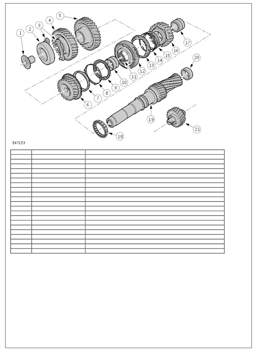
1
-
Retaining bolt
2
-
Ball bearing, layshaft
3
-
Retaining plate - bearing
4
-
Input pinion, layshaft
5
-
Gear - 6th gear
6
-
Gear wheel - 3rd gear
7
-
3rd gear synchroniser cone
8
-
Inner synchroniser ring
9
-
Outer synchroniser ring - 3rd gear
10
-
Needle bearing
11
-
Snap ring
12
-
3rd/4th gear synchroniser assembly
13
-
Outer synchroniser ring - 4th gear
14
-
Inner synchroniser ring
15
-
4th gear synchroniser cone
16
-
Gear wheel - 4th gear
17
-
Needle bearing
18
-
Centre bearing, layshaft
19
-
Layshaft
20
-
Roller bearing, layshaft
21
-
Reverse gear idler
The layshaft transfers the torque from the input shaft onto the output shaft. Gear wheels and gears and the 3rd/4th
gear synchroniser assembly are located on the shaft. First, 2nd and reverse gears are an integral part of the shaft.
The layshaft gearwheels and gears can be replaced individually. Because of improved manufacturing tolerances, it is no
longer necessary to change the gears and gear wheels in pairs.
The layshaft is a solid shaft. In order to prevent the shaft from moving axially, it is additionally secured with a retaining
bolt (1) and a bearing retaining plate (3).
The rotational direction of the output shaft is reversed by the use of the reverse gear idler (21).
OUTPUT SHAFT