Defender. Manual - part 122


  Index      Land Rover     Land Rover Defender - service manual 2007 year


Search            


Content   ..  120  121  122  123   ..


Defender. Manual - part 122


18. Using the special tool, release the fuel injection pump.

19. Remove the fuel injection pump.

Remove and discard the O-ring seal.

Installation

1. Install the fuel injection pump.

Clean the component mating faces.

Install a new O-ring seal.

Install the fuel injection pump bolts.

2. Secure the fuel injection pump.

Tighten the bolts to 23 Nm (17 lb.ft).

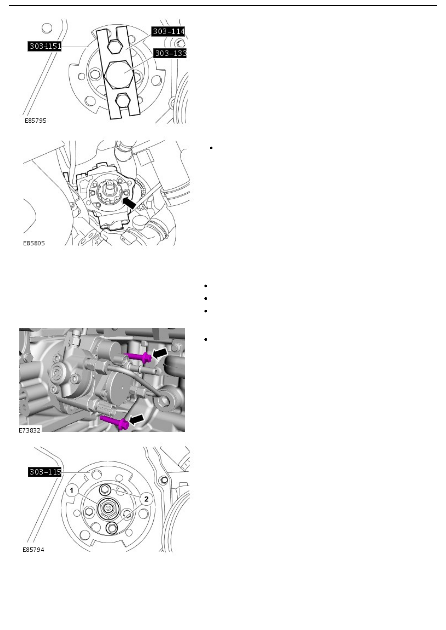
3. Secure the fuel injection pump drive gear.

1. Tighten the nut to 64 Nm (47 lb.ft).

2. Tighten the bolts to 33 Nm (24 lb.ft).

4. Remove the special tools.

4. Remove the special tools.

5. Using the special tool, install the fuel injection pump drive

gear cover.

6. NOTE: Remove and discard the blanking caps.

Loosely install a new high-pressure fuel line.

Loosely install the high-pressure pipe clamps.

7. Install the fuel injection pump high-pressure fuel line.

Tighten to 35 Nm (26 lb.ft).

8. Secure the fuel injection pump high-pressure fuel line.

1. Tighten to 10 Nm (7 lb.ft).

2. Tighten to 35 Nm (26 lb.ft).

9. Connect the fuel metering valve and the fuel temperature

sensor.

10. NOTE: Remove and discard the blanking caps.

Connect the fuel return line.

11. Secure the wiring harness to the inlet pipe.

12. Install the water pump.

12. Install the water pump.

Install a new gasket.

Tighten to 23 Nm (17 lb.ft).

13. Fill and bleed the cooling system. 

For additional information, refer to: 

Cooling System Draining,

Filling and Bleeding

 (303-03 Engine Cooling - 2.4L Duratorq-

TDCi HPCR (103kW/140PS) - Puma, General Procedures).

14. Install the brake vacuum pump. 

For additional information, refer to: 

Brake Vacuum Pump

(206-07 Power Brake Actuation, Removal and Installation).

15. Install the accessory drive component bracket. 

For additional information, refer to: 

Accessory Drive

Component Bracket

 (303-05 Accessory Drive - 2.4L Duratorq-

TDCi HPCR (103kW/140PS) - Puma, Removal and

Installation).

16. Connect the battery ground cable. 

For additional information, refer to: 

Battery Connect

 (414-01

Battery, Mounting and Cables, General Procedures).

17. Using the Land Rover approved diagnostic system carry out

the fuel injection pump learn procedure.

Fuel Charging and Controls - 2.4L Duratorq-TDCi HPCR (103kW/140PS) -

Puma - Fuel Metering Valve

Removal and Installation

Removal

• WARNINGS:

 The spilling of fuel is unavoidable during this operation. Make sure that all necessary precautions are taken to

prevent fire and explosion.

 Do not carry or operate cellular phones when working on or near any fuel related components. Highly flammable

vapors are always present and may ignite. Failure to follow these instructions may result in personal injury.

 Do not smoke or carry lighted tobacco or open flame of any type when working on or near any fuel related

components. Highly flammable vapors are always present and may ignite. Failure to follow these instructions may result

in personal injury.

 If fuel contacts the eyes, flush the eyes with cold water or eyewash solution and seek immediate medical

attention.

 Wash hands thoroughly after fuel handling, as prolonged contact may cause irritation. Should irritation develop,

seek medical attention.

 Do not carry out any repairs to the fuel system with the engine running. The fuel pressure within the system can

be as high as 2000 bar (29,008 lb-sq-in). Failure to follow this instruction may result in personal injury.

CAUTION: Diesel fuel injection equipment is manufactured to very precise tolerances and fine clearances. It is

therefore essential that absolute cleanliness is observed when working with these components. Always install new

blanking plugs to any open orifices or lines. Failure to follow this instruction may result in foreign matter ingress to the

fuel injection system.

1. Open the front door.
2. Remove the front seat cushion assembly.
3. Remove the battery cover.
4. Disconnect the battery ground cable. 

For additional information, refer to: 

Battery Disconnect and

Connect

 (414-01 Battery, Mounting and Cables, General

Procedures).

5. Open the bonnet.

6. Disconnect the fuel metering valve electrical connector.

7. Remove the 2 fuel metering valve securing bolts.


Content   ..  120  121  122  123   ..