Defender. Manual - part 80


  Index      Land Rover     Land Rover Defender - service manual 2007 year


Search            


Content   ..  78  79  80  81   ..


Defender. Manual - part 80


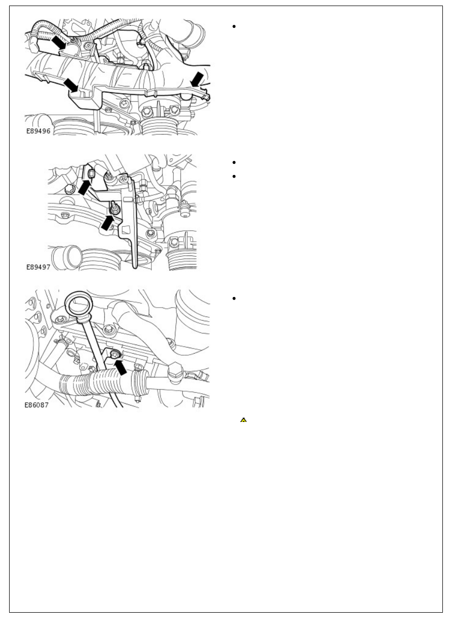
19. Release the engine wiring harness.

Release the 3 clips.

20. Release the engine wiring harness support bracket.

Remove the bolt.

Remove the nut.

21. Release the oil level indicator tube.

Remove the bolt.

CAUTION: Remove the bolts in the sequence

22. 

CAUTION: Remove the bolts in the sequence

shown. Failure to follow this instruction may result in

damage to the vehicle.

Remove the camshaft carrier.

Remove the 25 bolts.

23. Remove both of the camshafts.

Installation

All vehicles

1. 

CAUTION: Do not turn the crankshaft when the special

tool is fully located into the flywheel. Failure to follow this

instruction may result in damage to the vehicle.

Rotate the crankshaft to 50 degrees before top dead center

(BTDC).

Install the special tool through the CKP sensor hole.

2. NOTE: Clean the component mating face.

2. NOTE: Clean the component mating face.

Apply a 2.5 mm (0.1 inches) diameter bead of the specified

sealant to the cylinder head.

3. NOTE: Clean the component mating faces.

Install both of the camshafts.

Lubricate the camshaft journals and the camshaft lobes

with clean engine oil.

CAUTION: Tighten the bolts in the sequence shown,

4. 

CAUTION: Tighten the bolts in the sequence shown,

failure to follow this instruction may result in damage to the

vehicle.

• NOTE: Clean the component mating face.

Install the camshaft carrier.

Stage 1: Tighten the bolts 1 through 22 to 23 Nm (16

lb.ft).

Stage 2: Tighten the bolts 23 through 25 to 10 Nm (7

lb.ft).

5. Secure the oil level indicator tube.

Tighten bolt to 10 Nm (7 lb.ft).

6. Secure the engine wiring harness support bracket.

Tighten nut to 10 Nm (7 lb.ft).

Tighten bolt to 10 Nm (7 lb.ft).

7. Secure the engine wiring harness.

Secure the clips.

8. Install the generator mounting bracket.

Tighten the bolts to 25 Nm (18 lb.ft).

9. Install the turbocharger heat shield bracket.

Tighten the M6 bolt to 10 Nm (7 lb.ft).

Tighten the M8 bolt to 20 Nm (15 lb.ft).

10. Install the turbocharger heatshield.

Tighten to 7 Nm (5 lb.ft).

Vehicles with air conditioning

11. Install the A/C compressor. 

For additional information, refer to: 

Air Conditioning (A/C)

Compressor

 (412-03 Air Conditioning - 2.4L Duratorq-TDCi

HPCR (103kW/140PS) - Puma, Removal and Installation).

All vehicles

CAUTION: Make sure the colored links align to the


Content   ..  78  79  80  81   ..