Defender. Manual - part 40


  Index      Land Rover     Land Rover Defender - service manual 2007 year


Search            


Content   ..  38  39  40  41   ..


Defender. Manual - part 40


Hydraulic Brake Actuation - Brake Master Cylinder

Removal and Installation

Removal

1. Disconnect battery negative lead.

2. 

CAUTION: Do not allow brake fluid to contact paint

finished surfaces as paint may be damaged. If spilled, remove

fluid and clean are with clean warm water.

Place a container under the master cylinder to collect any

brake fluid spillage.

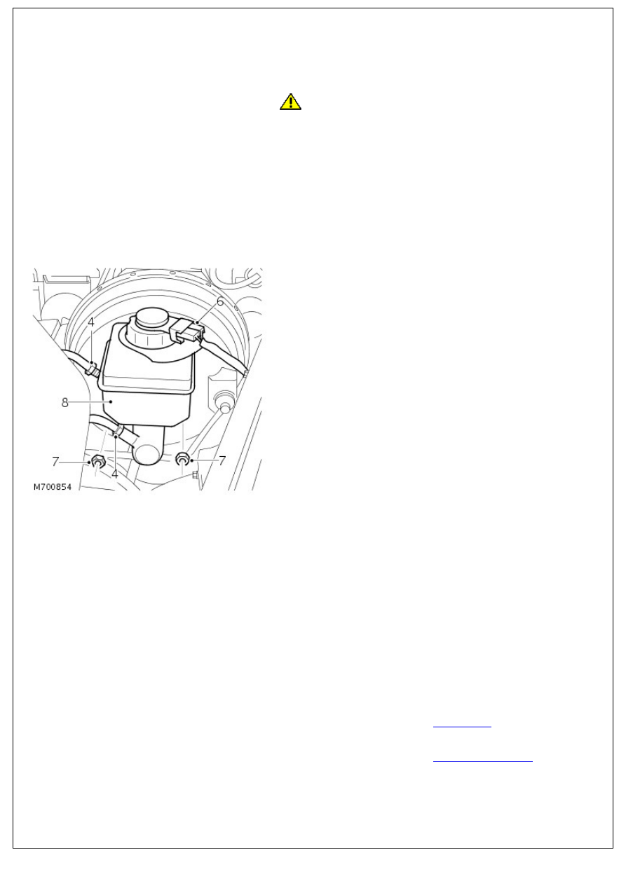
3. Clean area around master cylinder ports.
4. Loosen 2 unions securing brake pipes to master cylinder

ports.

5. Disconnect both brake pipes from master cylinder. Cover,

not plug, pipe ends to prevent entry of dirt.

6. Release 2 connectors from reservoir cap.
7. Remove 2 nuts securing master cylinder to brake booster.

8. Withdraw master cylinder from booster and remove.

9. Carefully ease reservoir from master cylinder by rolling it

from seals.

10. NOTE: Master cylinder to reservoir seals are different sizes.

Remove seals from master cylinder.

Installation

1. Instal NEW seals to master cylinder, ensuring seals are fitted

to correct ports.

2. Instal reservoir to master cylinder.
3. Ensuring that water ingress seal is in position, instal master

cylinder to booster.

4. Instal nuts securing master cylinder to booster and tighten

to 26 Nm (19 lbf.ft).

5. Connect brake pipes to master cylinder and tighten unions

to 15 Nm (11 lbf.ft).

6. Instal connectors to reservoir cap.
7. Fill reservoir with recommended brake fluid. 

For additional information, refer to: 

Specifications

 (206-00

Brake System - General Information, Specifications).

8. Bleed the brake system. 

For additional information, refer to: 

Brake System Bleeding

(206-00 Brake System - General Information, General

Procedures).

Hydraulic Brake Actuation - Brake Pedal and Bracket

Removal and Installation

Removal

1. Disconnect the battery ground cable. 

For additional information, refer to: 

Battery Disconnect and

Connect

 (414-01 Battery, Mounting and Cables, General

Procedures).

2. Remove the brake booster. 

For additional information, refer to: 

Brake Booster

 (206-07

Power Brake Actuation, Removal and Installation).

3. Remove the stoplamp switches. 

For additional information, refer to: 

Stoplamp Switch

 (417-01

Exterior Lighting, Removal and Installation).

4. Remove the floor covering.

Remove the 2 clips.

5. Release the interior lamp switch.

Remove the screw.

6. Remove the interior lamp switch.

Disconnect the electrical connector.

7. Release the front door aperture seal.

7. Release the front door aperture seal.

8. Remove the A-pillar trim panel.

Remove the 2 screws.

9. Release the floor covering away from the bulkhead.

10. Remove the stoplamp switch support bracket.

Remove the 2 bolts.

11. Release the brake pedal and bracket.

11. Release the brake pedal and bracket.

Remove the 6 bolts.

12. Remove the brake pedal and bracket.

Installation

1. To install, reverse the removal procedure.

Tighten to 25 Nm (18 lb.ft).

2. Tighten to 9 Nm (7 lb.ft).

3. Connect the battery ground cable. 

For additional information, refer to: 

Battery Connect

 (414-01

Battery, Mounting and Cables, General Procedures).


Content   ..  38  39  40  41   ..