Defender. Manual - part 37


  Index      Land Rover     Land Rover Defender - service manual 2007 year


Search            


Content   ..  35  36  37  38   ..


Defender. Manual - part 37


Front Disc Brake - Brake Pads

Removal and Installation

Removal

1. Remove front road wheels.
2. Clean exterior of calipers.
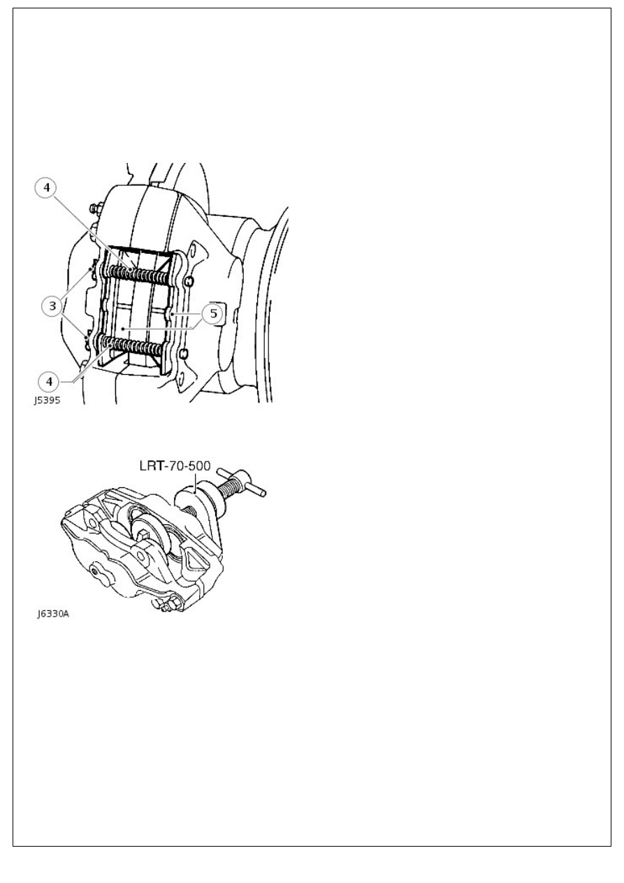
3. Remove split pin from retaining pins.
4. Remove pad retaining pins and anti-rattle springs.

5. Remove brake pads.

6. Clean exposed parts of pistons, using new brake fluid. Wipe

away excess with a lint free cloth.

7. Using piston clamp LRT-70-500 press each piston back into

its bore. Ensure that displaced brake fluid does not

overflow from reservoir.

Installation

1. Instal brake pads.

• NOTE: Ensure pads are correctly fitted, with leading edge chamfer fitted as shown.

2. Instal pad retaining pins and anti-rattle springs. Secure

2. Instal pad retaining pins and anti-rattle springs. Secure

with new split pins.

3. Apply brake pedal several times to locate pads.
4. Instal road wheels, remove chassis stands and jack. Tighten

wheel nuts to 130 Nm (96 lbf.ft).

5. Check fluid reservoir. Top up if necessary, using correct

grade of fluid. 

For additional information, refer to: 

Specifications

 (206-00

Brake System - General Information, Specifications).

Front Disc Brake - Brake Caliper

Removal and Installation

Removal

1. Loosen front road wheel nuts.

2. 

WARNING: Support on safety stands.

Raise front of vehicle.

3. Remove road wheel.
4. Remove split pins from pad retaining pins.
5. Remove brake pad retainers and springs.
6. Remove brake pads and shim if fitted.
7. Pull back brake hose shield.
8. Clamp brake hose using a suitable clamp.
9. Position container beneath brake caliper to collect spillage.
10. Loosen brake pipe union and disconnect from caliper.
11. Plug brake pipe and caliper connections.

12. Remove 2 bolts securing caliper.

13. Remove brake caliper.

WARNING: Do not separate caliper halves

14. Clean outer surfaces of caliper using aerosol brake cleaner.

15. Using special tool LRT-70-500, clamp pistons in inboard

half of caliper. Gently, keeping fingers clear, and with

CAUTION , apply air pressure to fluid inlet port to expel

pistons. It is unlikely that pistons will expel at same time,

regulate rate with a suitable piece of wood between

appropriate piston and caliper.

16. Finally remove pistons, identifying them with their

respective bores.

17. Remove wiper seal retainer by inserting a blunt screwdriver

between retainer and seal. Pry retainer carefully from mouth

of bore.

18. Taking care not to damage seal grooves, extract wiper seal

and fluid seal.

19. Clean bores, pistons and seal grooves using clean brake

fluid only. If caliper or pistons are corroded, or their condition

is not perfect, new parts must be fitted.

20. Coat new fluid seal with brake fluid. Ease seal into groove

in bore using only fingers, ensuring it is properly seated. Fluid

seal and groove are not same in section, so when seal is

seated it feels raised to touch at edge furthest away from

mouth of bore.

21. Coat appropriate piston with brake fluid. Insert it squarely

into bore by hand only. Do not tilt piston during insertion,

leave approximately 8mm projecting from bore.

22. Coat new wiper seal with brake fluid and fit to new seal

retainer. Slide assembly, seal first, over protruding piston and

into bore recess. Use piston clamp to press home seal

retainer and piston.

23. Clamp outboard pistons and carry out same procedure for

removing and fitting outboard pistons and seals.

Installation

1. Clean caliper to hub mating faces.
2. Position caliper to hub, install bolts and tighten to 82 Nm (60

lbf.ft).

3. Remove plugs from pipe to caliper connections and wipe.
4. Connect pipe to caliper, tighten union to 15 Nm (11 lbf.ft).
5. Apply a light film of grease to rear of brake pads.

6. Install pads to calipers. From 02MY, ensure pads are

correctly fitted, with leading edge chamfer fitted as shown.

7. Install pad retainers and springs.
8. Install split pins to retainers.
9. Remove brake hose clamp.


Content   ..  35  36  37  38   ..