Defender. Manual - part 34


  Index      Land Rover     Land Rover Defender - service manual 2007 year


Search            


Content   ..  32  33  34  35   ..


Defender. Manual - part 34


Brake System - General Information - Brake System

Description and Operation

Master cylinder description

The mechanical components of the hydraulic braking system consists of four piston caliper disc brakes at the front and

two piston caliper disc brakes at the rear.

Vented front brake discs are fitted as standard on 110/130 models, while 90 models have solid discs. However, on 90

models with a heavy duty chassis, vented front discs may also be fitted.

A cable controlled parking brake operates a single drum brake mounted on the output shaft of the transfer gearbox and

is completely independent of the main braking system.

The basic hydraulic system involves 2 separate and independent primary and secondary circuits which permits a degree

of braking should a fault occur in one of the circuits. The primary circuit operates the rear brake calipers and the

secondary circuit the front brake calipers.

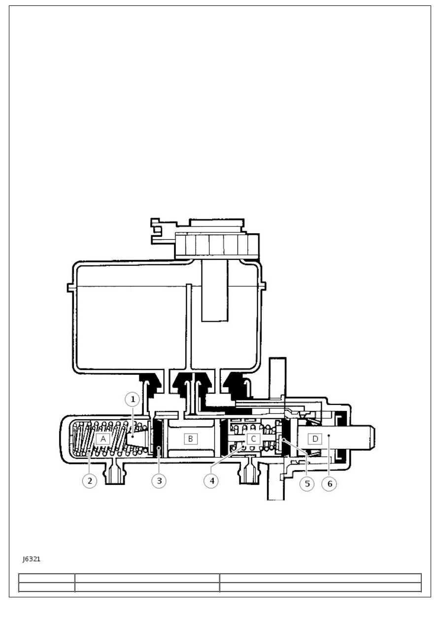
Master cylinder components

Item

Part Number

Description

1

-

Secondary plunger

2

-

Secondary spring

3

-

Recuperation seal

4

-

Primary spring

5

-

Recuperation seal

6

-

Primary plunger

Master cylinder operation

A tandem master cylinder, which is assisted by a light weight, short, compact servo, is fed by a divided fluid reservoir.

The rear section supplies fluid for the primary circuit and the front section the secondary circuit.

When the brakes are off, the fluid can move unrestricted between the dual line system and the separate reservoirs in the

fluid supply tank.

When the footbrake is applied, the primary plunger assembly moves up the cylinder bore and the pressure created acts

in conjunction with the primary spring to overcome the secondary springs, thus moving the secondary plunger assembly

up the bore. At the same time initial movement of both plungers takes the recuperating seals past the cut-off holes in

the cylinder chambers 'A' and 'C', see J6321, and applies pressure to the fluid in those chambers, which is directed to

the respective circuits.

The fluid in chambers 'B' and 'D' is unaffected by movement of the plungers and can move unrestricted between the

separate chambers and respective reservoirs in the fluid supply tank, both before and during brake application. When

the brakes are released, the plunger assemblies, aided by the return springs are retracted faster than the fluid; this

creates a depression between the fluid in chambers 'A' and 'C' and the recuperation seals.

The recuperation seals momentarily collapse allowing fluid in chambers 'B' and 'D' to flow through the holes in the

plungers, over the collapsed seals and into chambers 'A' and 'C' respectively. The movement of fluid from one set of

chambers to the other, is compensated for by fluid from the separate reservoirs in the supply tank moving through the

feed holes in the cylinder. Conversely, the final return movement of the plunger assemblies causes the extra fluid in

chambers 'A' and 'C' to move through the cut off holes into the fluid reservoir.

The servo unit provides controlled power assistance to the brake pedal when pressure is applied. Power is obtained from

a vacuum pump located on the RH side of the engine cylinder block. The vacuum is applied to both sides of a flexing

diaphragm, and by admitting atmospheric pressure to the rear diaphragm, assistance is obtained. The servo unit is

mounted between the brake pedal and master cylinder and is linked to these by push rods. Should a vacuum failure

occur, the two push rods will act as a single rod allowing the brakes to function in the normal way, although more effort

will be required to operate the brake pedal.

Master cylinder overhaul components

Item

Part Number

Description

1

-

Water ingress seal

2

-

Transfer housing

3

-

Vacuum seal

4

-

Guide ring

5

-

Retaining ring

6

-

O-ring seal

7

-

Primary plunger assembly

8

-

'L' seal

9

-

Secondary plunger

10

-

Washer

11

-

Recuperating seal (primary cup)

12

-

Seal retainer

13

-

Springs

14

-

Swirl tube

15

-

Master cylinder body

16

-

Reservoir seals

17

-

Reservoir

18

-

Low fluid level switch and cap

Hydraulic system

The brake system should be drained and flushed at the recommended service intervals.

A brake fluid loss switch is fitted to the master cylinder reservoir filler cap. The switch is wired to a warning light on the

vehicle fascia and will illuminate as a bulb check when the ignition is switched on and extinguishes when the engine is

running and the handbrake is released. A hydraulic failure in the system will result in fluid loss, causing the warning

light to illuminate.

On 90 models a pressure reducing valve (PRV), fitted to the RH bulkhead in the engine compartment, maintains the

braking balance, see J6322. Pressure to the rear calipers is regulated by the PRV, this valve is of the failure by-pass

type, allowing full system pressure to the rear brake calipers in the event of a front (secondary) circuit failure.

90 Models

110/130 Models

• NOTE: In some countries, a pressure reducing valve may be fitted to 110 models to conform to legal requirements.


Content   ..  32  33  34  35   ..