Jeep Wrangler (2023 year). Manual in english - page 10
 

  Index      Manuals     Jeep Wrangler (2023 year). Manual in english


Search            copyright infringement  


Content      ..     8      9      10      11     ..


Jeep Wrangler (2023 year). Manual in english - page 10


STARTING AND OPERATING

153

(Continued)

Adaptive Cruise Control (ACC) Operation

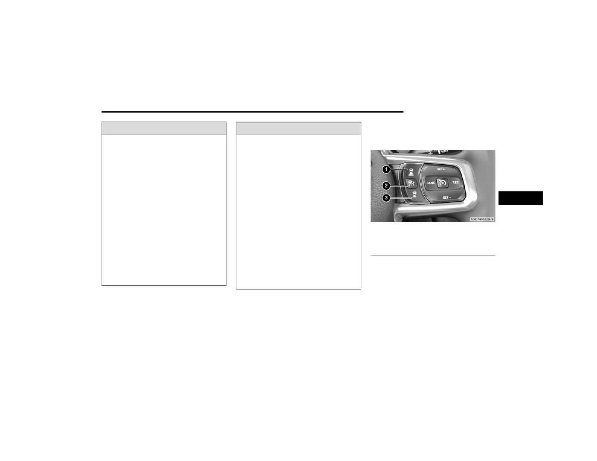
The buttons on the right side of the steering wheel operate 

the ACC system.

Adaptive Cruise Control Buttons

Adaptive Cruise Control (ACC) Menu

The instrument cluster display will show the current ACC 

system settings. The information it displays depends on 

ACC system status.
Push the Adaptive Cruise Control (ACC) on/off button until 

one of the following appears in the instrument cluster 

display:

WARNING!

Adaptive Cruise Control (ACC) is a convenience 

system. It is not a substitute for active driver involve

-

ment. It is always the driver’s responsibility to be 

attentive of road, traffic, and weather conditions, 

vehicle speed, distance to the vehicle ahead and, 

most importantly, brake operation to ensure safe 

operation of the vehicle under all road conditions. 

Your complete attention is always required while 

driving to maintain safe control of your vehicle. 

Failure to follow these warnings can result in a colli

-

sion and death or serious personal injury.

The ACC system:

Does not react to pedestrians, oncoming vehi

-

cles, and stationary objects (e.g., a stopped 

vehicle in a traffic jam or a disabled vehicle).

Cannot take street, traffic, and weather condi

-

tions into account, and may be limited upon 

adverse sight distance conditions.

Does not always fully recognize complex driving 

conditions, which can result in wrong or missing 

distance warnings.

On vehicles with an automatic transmission, will 

bring the vehicle to a complete stop while 

following a vehicle ahead and hold the vehicle 

for two seconds in the stop position. If the 

vehicle ahead does not start moving within two 

seconds, the ACC system will display a message 

that the system will release the brakes and that 

the brakes must be applied manually. An 

audible chime will sound when the brakes are 

released.

You should not utilize the ACC system:

When driving in fog, heavy rain, heavy snow, 

sleet, heavy traffic, and complex driving situa

-

tions (i.e., in highway construction zones).

When entering a turn lane or highway off-ramp; 

when driving on roads that are winding, icy, 

snow-covered, slippery, or have steep uphill or 

downhill slopes.

When towing a trailer up or down steep slopes.

When circumstances do not allow safe driving at 

a constant speed.

WARNING!

1 — Distance Setting Increase
2 — Adaptive Cruise Control (ACC) On/Off
3 — Distance Setting Decrease

4

154

STARTING AND OPERATING


Adaptive Cruise Control Off
When ACC is deactivated, the display will read “Adaptive 

Cruise Control Off.”
Adaptive Cruise Control Ready
When ACC is activated, but the vehicle speed setting has 

not been selected, the display will read “Adaptive Cruise 

Control Ready.”
Adaptive Cruise Control Set
When the SET (+) or the SET (-) button is pushed, the 

display will read “ACC SET.”
When ACC is set, the set speed will show in the instrument 

cluster display.
The ACC screen may display once again if any of the 

following ACC activity occurs:

System Cancel

Driver Override

System Off

ACC Proximity Warning

ACC Unavailable Warning

The instrument cluster display will return to the last 

display selected after five seconds of no ACC display 

activity.

Activating Adaptive Cruise Control (ACC)

The minimum set speed for the ACC system is 20 mph 

(32 km/h).
When the system is turned on and in the ready state, the 

instrument cluster displays “ACC Ready.”
When the system is off, the instrument cluster displays 

“Adaptive Cruise Control (ACC) Off.”

NOTE:

You cannot engage ACC under the following conditions: 

When in 4WD Low

When the brakes are applied

When the parking brake is applied

When the automatic transmission is in PARK, REVERSE 

or NEUTRAL

When the manual transmission is in FIRST gear

When the vehicle speed is below 20 mph (32 km/h) 

(manual transmission)

When the vehicle speed is below the minimum speed 

range

When the brakes are overheated

When the driver’s door is open at low speeds

When the driver’s seat belt is unbuckled at low speeds

When ESC Full Off mode is active

When Off Road+ (if equipped) is active

To Activate/Deactivate

Push and release the Adaptive Cruise Control (ACC) on/off 

button. The ACC menu in the instrument cluster display 

will read “ACC Ready.”
To turn the system off, push and release the Adaptive 

Cruise Control (ACC) on/off button again. At this time, the 

system will turn off and the instrument cluster display will 

read “Adaptive Cruise Control (ACC) Off.”

To Set A Desired Speed

When the vehicle reaches the speed desired, push the 

SET (+) button or the SET (-) button and release. The 

instrument cluster display will show the set speed.

NOTE:

Fixed Speed Cruise Control can be used without ACC 

enabled. To change between the different modes, push 

the ACC on/off button which turns the ACC and the Fixed 

Speed Cruise Control off. Pushing the Fixed Speed Cruise 

Control on/off button will result in turning on (changing to) 

Fixed Speed Cruise Control mode.

WARNING!

Leaving the Adaptive Cruise Control (ACC) system on 

when not in use is dangerous. You could accidentally 

set the system or cause it to go faster than you want. 

You could lose control and have a collision. Always leave 

the system off when you are not using it.

WARNING!

In Fixed Speed Cruise Control mode, the system will not 

react to vehicles ahead. In addition, the proximity 

warning does not activate and no alarm will sound even 

if you are too close to the vehicle ahead since neither 

the presence of the vehicle ahead nor the 

vehicle-to-vehicle distance is detected. Be sure to 

maintain a safe distance between your vehicle and the 

vehicle ahead. Always be aware which mode is 

selected.

STARTING AND OPERATING

155

If ACC is set when the vehicle speed is below 20 mph 

(32 km/h), the set speed will default to 20 mph

(32 km/h).

NOTE:

Fixed Speed Cruise Control cannot be set below 20 mph 

(32 km/h).
If either system is set when the vehicle speed is above 

20 mph (32 km/h), the set speed shall be the current 

speed of the vehicle.
On vehicles equipped with a manual transmission, the 

ACC system cannot be set when the vehicle speed is below 

20 mph (32 km/h) or when the vehicle is in FIRST gear.

NOTE:

Keeping your foot on the accelerator pedal can cause 

the vehicle to continue to accelerate beyond the set 

speed. If this occurs, the message “DRIVER OVERRIDE” 

will display in the instrument cluster display.

If you continue to accelerate beyond the set speed 

while ACC is enabled, the system will not be controlling 

the distance between your vehicle and the vehicle 

ahead. The vehicle speed will only be determined by 

the position of the accelerator pedal.

To Cancel

The following conditions cancel the ACC or Fixed Speed 

Cruise Control systems:

The brake pedal is applied

The CANC button is pushed

The Anti-Lock Brake System (ABS) activates

The gear selector is removed from the DRIVE position

The Electronic Stability Control/Traction Control 

System (ESC/TCS) activates

The vehicle parking brake is applied

The braking temperature exceeds normal range (over

-

heated)

The Trailer Sway Control (TSC) activates

The vehicle speed is less than 15 mph (24 km/h) 

(manual transmission only)

The clutch is pressed for more than 10 seconds 

(manual transmission only)

The vehicle is placed in NEUTRAL for more than 

10 seconds (manual transmission only)

The driver shifts to FIRST gear (manual transmission 

only)

The following conditions will only cancel the ACC system:

Driver seat belt is unbuckled at low speeds

Driver door is opened at low speeds

To Turn Off

The system will turn off and erase the set speed in 

memory if:

The Adaptive Cruise Control (ACC) on/off button is 

pushed

The Fixed Speed Cruise Control on/off button is pushed

The ignition is placed in the OFF position

4WD Low is engaged

To Resume

If there is a set speed in the memory, push the RES button 

and then remove your foot from the accelerator pedal. The 

instrument cluster display will show the last set speed.

Resume can be used at any speed above 20 mph

(32 km/h) when only Fixed Speed Cruise Control is being 

used.
Resume can be used at any speed above 0 mph (0 km/h) 

when ACC is active.

NOTE:

While in ACC mode, when the vehicle comes to a 

complete stop longer than two seconds, the system will 

cancel. The driver will have to apply the brakes to keep 

the vehicle at a standstill.

ACC cannot be resumed if there is a stationary vehicle 

in front of your vehicle in close proximity.

To Vary The Speed Setting 

To Increase Or Decrease The Set Speed
After setting a speed, you can increase the set speed by 

pushing the SET (+) button, or decrease speed by pushing 

the SET (-) button.

WARNING!

The Resume function should only be used if traffic and 

road conditions permit. Resuming a set speed that is 

too high or too low for prevailing traffic and road condi

-

tions could cause the vehicle to accelerate or deceler

-

ate too sharply for safe operation. Failure to follow 

these warnings can result in a collision and death or 

serious personal injury.

4

156

STARTING AND OPERATING


U.S. Speed (mph)

Pushing the SET (+), or SET (-) button once will result in 

a 1 mph speed adjustment. Each subsequent tap of 

the button results in an adjustment of 1 mph.

If the button is continually pushed, the set speed will 

continue to adjust in 5 mph increments until the button 

is released. The new set speed is reflected in the instru

-

ment cluster display.

Metric Speed (km/h)

Pushing the SET (+), or SET (-) button once will result in 

a 1 km/h speed adjustment. Each subsequent tap of 

the button results in an adjustment of 1 km/h.

If the button is continually pushed, the set speed will 

continue to adjust in 10 km/h increments until the 

button is released. The new set speed is reflected in 

the instrument cluster display.

NOTE:

When you override and push the SET (+) button or SET (-) 

buttons, the new set speed will be the current speed of the 

vehicle.
When ACC Is Active

When you use the SET (-) button to decelerate, if the 

engine’s braking power does not slow the vehicle suffi

-

ciently to reach the set speed, the brake system will 

automatically slow the vehicle.

The ACC system applies the brake down to a full stop 

when following the vehicle in front. If your vehicle 

follows the vehicle in front to a standstill, your vehicle 

will release the brakes two seconds after coming to a 

full stop.

The ACC system maintains set speed when driving 

uphill and downhill. However, a slight speed change on 

moderate hills is normal. In addition, downshifting may 

occur while climbing uphill or descending downhill. This 

is normal operation and necessary to maintain set 

speed. When driving uphill and downhill, the ACC 

system will cancel if the braking temperature exceeds 

normal range (overheated).

Setting The Following Distance In ACC

The specified following distance for ACC can be set by 

varying the distance setting between four bars (longest), 

three bars (long), two bars (medium) and one bar (short). 

Using this distance setting and the vehicle speed, ACC 

calculates and sets the distance to the vehicle ahead. This 

distance setting displays in the instrument cluster display.

Distance Settings

To increase the distance setting, push the Distance 

Setting Increase button and release. Each time the button 

is pushed, the distance setting increases by one bar 

(longer).
To decrease the distance setting, push the Distance 

Setting Decrease button and release. Each time the 

button is pushed, the distance setting decreases by one 

bar (shorter).
If there is no vehicle ahead, the vehicle will maintain the 

set speed. If a slower moving vehicle is detected in the 

same lane, the instrument cluster displays the ACC Set 

With Target Light. The system will then adjust vehicle 

speed automatically to maintain the distance setting, 

regardless of the set speed.
The vehicle will then maintain the set distance until:

The vehicle ahead accelerates to a speed above the 

set speed

The vehicle ahead moves out of your lane or view of the 

sensor

The distance setting is changed

The system disengages  

Ú

page 154

The maximum braking applied by ACC is limited; however, 

the driver can always apply the brakes manually, if 

necessary.

NOTE:

The brake lights will illuminate whenever the ACC system 

applies the brakes.
A Proximity Warning will alert the driver if ACC predicts that 

its maximum braking level is not sufficient to maintain the 

set distance. If this occurs, a visual alert “BRAKE!” will 

1 — Longest Distance Setting (Four Bars)
2 — Medium Distance Setting (Two Bars)
3 — Long Distance Setting (Three Bars)
4 — Short Distance Setting (One Bar)

STARTING AND OPERATING

157

flash in the instrument cluster display and a chime will 

sound while ACC continues to apply its maximum braking 

capacity.

NOTE:

The “BRAKE!” screen in the instrument cluster display is a 

warning for the driver to take action and does not neces

-

sarily mean that the Forward Collision Warning system is 

applying the brakes autonomously.

Overtake Aid

When driving with ACC engaged and following a vehicle, 

the system will provide an additional acceleration up to 

the ACC set speed to assist in passing the vehicle. This 

additional acceleration is triggered when the driver utilizes 

the left turn signal and will only be active when passing on 

the left hand side.

ACC Operation At A Stop (Automatic 

Transmission Only)

In the event that the ACC system brings your vehicle to a 

standstill while following a target vehicle, your vehicle will 

resume motion without the need for any driver action if the 

target vehicle starts moving within two seconds of your 

vehicle coming to a standstill.
If the target vehicle does not start moving within two 

seconds of your vehicle coming to a standstill, the ACC 

with Stop system will cancel and the brakes will release. A 

cancel message will display on the instrument cluster 

display and produce a warning chime. Driver intervention 

will be required at this moment.
While ACC with Stop is holding your vehicle at a standstill, 

if the driver seatbelt is unbuckled or the driver door is 

opened, the ACC with Stop system will cancel and the 

brakes will release. A cancel message will display on the 

instrument cluster display and produce a warning chime. 

Driver intervention will be required at this moment.

Display Warnings And Maintenance

“WIPE FRONT RADAR SENSOR IN FRONT OF 

VEHICLE” WARNING

The “ACC/FCW Unavailable Wipe Front Radar Sensor” 

warning will display and a chime will sound when 

conditions temporarily limit system performance.
This most often occurs at times of poor visibility, such as 

in snow or heavy rain. The ACC system may also become 

temporarily blinded due to obstructions, such as mud, dirt 

or ice. In these cases, the instrument cluster display will 

display “ACC/FCW Unavailable Wipe Front Radar Sensor” 

and the system will deactivate.
The “ACC/FCW Unavailable Wipe Front Radar Sensor” 

message can sometimes be displayed while driving in 

highly reflective areas (i.e. tunnels with reflective tiles, or 

ice and snow). The ACC system will recover after the 

vehicle has left these areas. Under rare conditions, when 

the radar is not tracking any vehicles or objects in its path 

this warning may temporarily occur.

NOTE:

If the “ACC/FCW Unavailable Wipe Front Radar Sensor” 

warning is active, Fixed Speed Cruise Control is still 

available.
If weather conditions are not a factor, the driver should 

examine the sensor. It may require cleaning or removal of 

an obstruction. The sensor is located in the center of the 

vehicle behind the lower grille.
To keep the ACC system operating properly, it is important 

to note the following maintenance items:

Always keep the sensor clean. Carefully wipe the 

sensor lens with a soft cloth. Be cautious not to 

damage the sensor lens.

Do not remove any screws from the sensor. Doing so 

could cause an ACC system malfunction or failure and 

require a sensor realignment.

If the sensor or front end of the vehicle is damaged due 

to a collision, see an authorized dealer for service.

Do not attach or install any accessories near the 

sensor, including transparent material or aftermarket 

grilles. Doing so could cause an ACC system failure or 

malfunction.

When the condition that deactivated the system is no 

longer present, the system will return to the “Adaptive 

Cruise Control Off” state and will resume function by 

simply reactivating it.

NOTE:

If the “ACC/FCW Unavailable Wipe Front Radar Sensor” 

message occurs frequently (e.g. more than once on every 

trip) without any snow, rain, mud, or other obstruction, 

have the radar sensor realigned at an authorized dealer.

WARNING!

When the ACC system is resumed, the driver must 

ensure that there are no pedestrians, vehicles or 

objects in the path of the vehicle. Failure to follow these 

warnings can result in a collision and death or serious 

personal injury.

4

158

STARTING AND OPERATING


“CLEAN FRONT WINDSHIELD” WARNING

The “ACC/FCW Limited Functionality Clean Front 

Windshield” warning will display and a chime will sound 

when conditions temporarily limit system performance. 

This most often occurs at times of poor visibility, such as 

in snow or heavy rain and fog. The ACC system may also 

become temporarily blinded due to obstructions, such as 

mud, dirt, or ice on windshield and fog on the inside of 

glass. In these cases, the instrument cluster display will 

display “ACC/FCW Limited Functionality Clean Front 

Windshield” and the system will have degraded 

performance.
The “ACC/FCW Limited Functionality Clean Front 

Windshield” message can sometimes be displayed while 

driving in adverse weather conditions. The ACC/FCW 

system will recover after the vehicle has left these areas. 

Under rare conditions, when the camera is not tracking 

any vehicles or objects in its path this warning may 

temporarily occur.
If weather conditions are not a factor, the driver should 

examine the windshield and the camera located on the 

back side of the inside rear view mirror. They may require 

cleaning or removal of an obstruction.
When the condition that created limited functionality is no 

longer present, the system will return to full functionality.

NOTE:

If the “ACC/FCW Limited Functionality Clean Front Wind

-

shield” message occurs frequently (e.g. more than once 

on every trip) without any snow, rain, mud, or other 

obstruction, have the windshield and forward facing 

camera inspected at an authorized dealer.

“SERVICE ACC/FCW” WARNING

If the system turns off, and the instrument cluster displays 

“ACC/FCW Unavailable Service Required” or “Cruise/FCW 

Unavailable Service Required”, there may be an internal 

system fault or a temporary malfunction that limits ACC 

functionality. Although the vehicle is still drivable under 

normal conditions, ACC will be temporarily unavailable. If 

this occurs, try activating ACC again later, following an 

ignition cycle. If the problem persists, see an authorized 

dealer.

Precautions While Driving With ACC

In certain driving situations, ACC may have detection 

issues. In these cases, ACC may brake late or 

unexpectedly. The driver needs to stay alert and may need 

to intervene. The following are examples of these types of 

situations:

TOWING A TRAILER

Towing a trailer is not recommended when using ACC.

OFFSET DRIVING

ACC may not detect a vehicle in the same lane that is 

offset from your direct line of travel, or a vehicle merging 

in from a side lane. There may not be sufficient distance 

to the vehicle ahead. The offset vehicle may move in and 

out of the line of travel, which can cause your vehicle to 

brake or accelerate unexpectedly.

Offset Driving Condition Example

TURNS AND BENDS

When driving on a curve with ACC engaged, the system 

may decrease the vehicle speed and acceleration for 

stability reasons, with no vehicle in front detected. Once 

the vehicle is out of the curve the system will resume your 

original set speed. This is a part of normal ACC system 

functionality.

NOTE:

On tight turns ACC performance may be limited.

STARTING AND OPERATING

159

USING ACC ON HILLS

ACC performance may be limited when driving on hills. 

ACC may not detect a vehicle in your lane depending on 

the speed, vehicle load, traffic conditions, and the 

steepness of the hill.

ACC Hill Example

LANE CHANGING

ACC may not detect a vehicle until it is completely in the 

lane in which you are traveling. In the following lane 

changing example, ACC has not yet detected the vehicle 

changing lanes and it may not detect the vehicle until it's 

too late for the ACC system to take action. ACC may not 

detect a vehicle until it is completely in the lane. There 

may not be sufficient distance to the lane-changing 

vehicle. Always be attentive and ready to apply the brakes 

if necessary.

Lane Changing Example

NARROW VEHICLES

Some narrow vehicles traveling near the outer edges of 

the lane or edging into the lane are not detected until they 

have moved fully into the lane. There may not be sufficient 

distance to the vehicle ahead.

Narrow Vehicle Example

STATIONARY OBJECTS AND VEHICLES

ACC does not react to stationary objects or vehicles. For 

example, ACC will not react in situations where the vehicle 

you are following exits your lane and the vehicle ahead is 

stopped in your lane. It will consider this stopped vehicle a 

stationary object as it did not previously detect movement 

from it. Always be attentive and ready to apply the brakes 

if necessary.

Stationary Object And Stationary Vehicle Example

4

160

STARTING AND OPERATING


PARKSENSE REAR PARK ASSIST —

IF EQUIPPED  

The ParkSense Rear Park Assist system provides visual 

and audible indications of the distance between the rear 

fascia/bumper and a detected obstacle when backing up 

(e.g. during a parking maneuver). For limitations of this 

system and recommendations, see  

Ú

page 163.

ParkSense will retain the last system state (enabled or 

disabled) from the last ignition cycle when the ignition is 

placed in the ON/RUN position.
ParkSense can be active only when the gear selector is in 

REVERSE. If ParkSense is enabled at this gear selector 

position, the system will remain active until the vehicle 

speed is increased to approximately 7 mph (11 km/h) or 

above. When in REVERSE and above the system's 

operating speed, a warning will appear within the 

instrument cluster display indicating the vehicle speed is 

too fast. The system will become active again if the vehicle 

speed is decreased to speeds less than approximately 

6 mph (9 km/h).

P

ARK

S

ENSE

 S

ENSORS

The four ParkSense sensors, located in the rear fascia/

bumper, monitor the area behind the vehicle that is within 

the sensors’ field of view. The sensors can detect 

obstacles from approximately 12 inches (30 cm) up to 

79 inches (200 cm) from the rear fascia/bumper in the 

horizontal direction, depending on the location, type and 

orientation of the obstacle.

P

ARK

S

ENSE

 W

ARNING

 D

ISPLAY

The ParkSense Warning screen is located within the 

instrument cluster display  

Ú

page 108. It provides visual 

warnings to indicate the distance between the rear fascia/

bumper and the detected obstacle.

P

ARK

S

ENSE

 D

ISPLAY

When the vehicle is in REVERSE, the instrument cluster 

display will show the Park Assist ready system status.
The system will indicate a detected obstacle by showing a 

single arc in one or more regions based on the obstacle’s 

distance and location relative to the vehicle.
If an obstacle is detected in the center rear region, the 

display will show a single solid arc in the center rear region 

and will produce a one-half second tone. As the vehicle 

moves closer to the obstacle, the display will show a single 

arc moving closer to the vehicle and emit a fast sound 

tone that will change from fast to continuous.
If an obstacle is detected in the left and/or right rear 

region, the display will show a single flashing arc in the left 

and/or right rear region and will produce a fast sound 

tone. As the vehicle moves closer to the obstacle, the 

display will show the single arc moving closer to the 

vehicle and the tone will change from fast to continuous.

STARTING AND OPERATING

161

Rear ParkSense Arcs

1 — Continuous Tone/Flashing Arc

4 — Slow Tone/Solid Arc

2 — Fast Tone/Flashing Arc

5 — Slow Tone/Solid Arc

3 — Fast Tone/Flashing Arc

6 — Single 1/2 Second Tone/Solid Arc

4

162

STARTING AND OPERATING


The vehicle is close to the obstacle when the warning display shows one flashing arc and sounds a continuous tone. The following chart shows the warning alert operation when the 

system is detecting an obstacle:

NOTE:

ParkSense will reduce the volume of the radio, if on, when 

the system is sounding an audio tone.

E

NABLING

 A

ND

 D

ISABLING

 P

ARK

S

ENSE

ParkSense can be enabled and disabled with 

the ParkSense switch located below the 

Uconnect display.

When the ParkSense switch is pushed to disable the 

system, the instrument cluster display  

Ú

page 108 will 

show the “PARKSENSE OFF” message for approximately 

five seconds. When the gear selector is moved to 

REVERSE and the system is disabled, the instrument 

cluster display will show the “PARKSENSE OFF” message 

for as long as the vehicle is in REVERSE (Not in 4WD Low).

The ParkSense switch LED will be on when ParkSense is 

disabled or requires service. The ParkSense switch LED 

will be off when the system is enabled. If the ParkSense 

switch is pushed, and requires service, the ParkSense 

switch LED will blink momentarily, and then the LED will 

remain on.

S

ERVICE

 T

HE

 P

ARK

S

ENSE

 R

EAR

 P

ARK


A

SSIST

 S

YSTEM

During vehicle start up, when the ParkSense Rear Park 

Assist System has detected a faulted condition, the 

instrument cluster display will actuate a single chime, 

once per ignition cycle, and it will display the “PARKSENSE 

UNAVAILABLE WIPE REAR SENSORS” or the “PARKSENSE 

UNAVAILABLE SERVICE REQUIRED” message.

When the gear selector is moved to REVERSE and the 

system has detected a faulted condition, the instrument 

cluster display will show the "PARKSENSE UNAVAILABLE 

WIPE REAR SENSORS" or "PARKSENSE UNAVAILABLE 

SERVICE REQUIRED" message for as long as the vehicle is 

in REVERSE. Under this condition, ParkSense will not 

operate.
If “PARKSENSE UNAVAILABLE WIPE REAR SENSORS” 

appears in the instrument cluster display, make sure the 

outer surface and the underside of the rear fascia/

bumper is clean and clear of snow, ice, mud, dirt or other 

obstruction and then cycle the ignition. If the message 

continues to appear, see an authorized dealer.
If “PARKSENSE UNAVAILABLE SERVICE REQUIRED” 

appears in the instrument cluster display, see an 

authorized dealer.

WARNING ALERTS

Rear Distance 

(inches/cm)

Greater than 

79 inches (200 cm)

79-59 inches 

(200-150 cm)

59-47 inches 

(150-120 cm)

47-39 inches 

(120-100 cm)

39-25 inches 

(100-65 cm)

25-12 inches

(65-30 cm)

Less than 

12 inches (30 cm)

Arcs — Left

None

None

None

None

None

2nd Flashing

1st Flashing

Arcs — Center

None

6th Solid

5th Solid

4th Solid

3rd Flashing

2nd Flashing

1st Flashing

Arcs — Right

None

None

None

None

None

2nd Flashing

1st Flashing

Audible Alert Chime

None

Single 1/2 Second 

Tone

(for rear center 

only)

Slow

(for rear center only)

Slow

(for rear center 

only)

Fast

(for rear center 

only)

Fast

Continuous

Radio Volume 

Reduced

No

Yes

Yes

Yes

Yes

Yes

Yes

STARTING AND OPERATING

163

C

LEANING

 T

HE

 P

ARK

S

ENSE

 S

YSTEM

Clean the Rear Park Assist sensors with water, car wash 

soap and a soft cloth. Do not use rough or hard cloths. In 

washing stations, clean sensors quickly keeping the vapor 

jet/high pressure washing nozzles at least 4 inches (10 

cm) from the sensors. Do not scratch or poke the sensors.

P

ARK

S

ENSE

 S

YSTEM

 U

SAGE


P

RECAUTIONS

NOTE:

Ensure that the rear fascia/bumper is free of snow, ice, 

mud, dirt and debris to keep the ParkSense system 

operating properly.

Jackhammers, large trucks, and other vibrations could 

affect the performance of ParkSense.

When you turn ParkSense off, the instrument cluster 

display will read “PARKSENSE OFF.” Furthermore, once 

you turn ParkSense off, it remains off until you turn it 

on again, even if you cycle the ignition.

ParkSense, when on, will reduce the volume of the 

radio when it is sounding a tone.

Clean the ParkSense sensors regularly, taking care not 

to scratch or damage them. The sensors must not be 

covered with ice, snow, slush, mud, dirt or debris. 

Failure to do so can result in the system not working 

properly. The ParkSense system might not detect an 

obstacle behind the fascia/bumper, or it could provide 

a false indication that an obstacle is behind the fascia/

bumper.

Use the ParkSense switch to turn the ParkSense 

system off if objects such as bicycle carriers, trailer 

hitches, etc. are placed within 12 inches (30 cm) of the 

rear fascia/bumper. Failure to do so can result in the 

system misinterpreting a close object as a sensor 

problem, causing the “PARKSENSE UNAVAILABLE 

SERVICE REQUIRED” message to be displayed in the 

instrument cluster display.

PARKVIEW REAR BACK UP CAMERA  

The ParkView Rear Back Up Camera allows you to see an 

on-screen image of the rear surroundings of your vehicle 

whenever the gear selector is put into REVERSE. The 

image will be displayed in the touchscreen display along 

with a caution note to “Check Entire Surroundings” across 

the top of the screen. After five seconds this note will 

disappear. The ParkView camera is located on the rear of 

the vehicle in the center of the spare tire.
Manual Activation Of The Rear View Camera
1. Press the Controls button located on the bottom of 

the Uconnect display.

2. Press the Back Up Camera button to turn the Rear 

View Camera system on.

WARNING!

Drivers must be careful when backing up even when 

using ParkSense. Always check carefully behind your 

vehicle, look behind you, and be sure to check for 

pedestrians, animals, other vehicles, obstructions, 

and blind spots before backing up. You are respon

-

sible for safety and must continue to pay attention to 

your surroundings. Failure to do so can result in 

serious injury or death.

Before using ParkSense, it is strongly recommended 

that the ball mount and hitch ball assembly be 

disconnected from the vehicle when the vehicle is 

not used for towing. Failure to do so can result in 

injury or damage to vehicles or obstacles because 

the hitch ball will be much closer to the obstacle than 

the rear fascia when the vehicle sounds the contin

-

uous tone. Also, the sensors could detect the ball 

mount and hitch ball assembly, depending on its size 

and shape, giving a false indication that an obstacle 

is behind the vehicle.

CAUTION!

ParkSense is only a parking aid and it is unable to 

recognize every obstacle, including small obstacles. 

Parking curbs might be temporarily detected or not 

detected at all. Obstacles located above or below the 

sensors will not be detected when they are in close 

proximity.

The vehicle must be driven slowly when using Park

-

Sense in order to be able to stop in time when an 

obstacle is detected. It is recommended that the 

driver looks over his/her shoulder when using Park

-

Sense.

4

164

STARTING AND OPERATING


(Continued)

When the vehicle is shifted out of REVERSE with Camera 

delay turned off, the rear Camera mode is exited and the 

previous screen appears again.
When the vehicle is shifted out of REVERSE with Camera 

delay turned on, the rear Camera image will be displayed 

for up to 10 seconds unless the vehicle speed exceeds 

8 mph (13 km/h), the transmission is shifted into PARK, 

the ignition is placed in the OFF position, or the 

touchscreen X button to disable display of the Rear View 

Camera image is pressed.
Whenever the Rear View Camera image is activated 

through the Back Up Camera button in the Controls menu, 

and the vehicle speed is greater than, or equal to, 8 mph 

(13 km/h), a display timer for the image is initiated. The 

image will continue to be displayed until the display timer 

exceeds 10 seconds.

NOTE:

If the vehicle speed remains below 8 mph (13 km/h), 

the Rear View Camera image will be displayed continu

-

ously until deactivated via the touchscreen X button, 

the transmission is shifted into PARK, or the ignition is 

placed in the OFF position.

The touchscreen X button to disable display of the 

camera image is made available ONLY when the 

vehicle is not in REVERSE.

When enabled, active guidelines are overlaid on the image 

to illustrate the width of the vehicle and its projected back 

up path based on the steering wheel position. A dashed 

center line overlay indicates the center of the vehicle to 

assist with parking or aligning to a hitch/receiver.
When enabled, fixed guidelines are overlaid on the image 

to illustrate the width of the vehicle.

Different colored zones indicate the distance to the rear of 

the vehicle.
The following table shows the approximate distances for 

each zone:

NOTE:

If snow, ice, mud, or any foreign substance builds up on 

the camera lens, clean the lens, rinse with water, and dry 

with a soft cloth. Do not cover the lens.

TRAILCAM SYSTEM — IF EQUIPPED

Your vehicle may be equipped with a TrailCam that allows 

you to you see an on-screen image of the front view of your 

vehicle. The image will be displayed on the touchscreen 

display along with a caution note “Check Entire 

Surroundings” across the top of the screen.

Front View Camera

Zone

Distance To The Rear Of The 

Vehicle

Red

0 - 1 ft (0 - 30 cm)

Yellow

1 ft - 6.5 ft (30 cm - 2 m)

Green

6.5 ft or greater 

(2 m or greater)

WARNING!

Drivers must be careful when backing up even when 

using the ParkView Rear Back Up Camera. Always 

check carefully behind your vehicle, and be sure to 

check for pedestrians, animals, other vehicles, 

obstructions, or blind spots before backing up. You are 

responsible for the safety of your surroundings and 

must continue to pay attention while backing up. 

Failure to do so can result in serious injury or death.

CAUTION!

To avoid vehicle damage, ParkView should only be 

used as a parking aid. The ParkView camera is 

unable to view every obstacle or object in your drive 

path.

To avoid vehicle damage, the vehicle must be driven 

slowly when using ParkView to be able to stop in time 

when an obstacle is seen. It is recommended that 

the driver look frequently over his/her shoulder when 

using ParkView.

CAUTION!

STARTING AND OPERATING

165

NOTE:

The system will stay active while in 4WD Low.
The TrailCam system has programmable settings that may 

be selected through the Uconnect system  

Ú

page 184.

Manual Activation Of The TrailCam
TrailCam view can be activated via the below methods:

Press the FWD Camera button on the controls screen.

Press the Forward Facing Camera button on the apps 

menu.

Press the TrailCam button on the Off Road Pages.

Press the Off Road+ button when “Auto Launch Off 

Road+” (if equipped) has been selected under camera 

settings.

The TrailCam view can also be activated by pressing the 

 icon on the Back Up Camera view. The Back Up 

Camera view can also be activated by pressing the 


icon on the TrailCam view.
When the vehicle is shifted out of REVERSE with Camera 

Delay turned off and TrailCam view is active, the TrailCam 

mode is exited and the previous screen appears again.
When the vehicle is shifted out of REVERSE with Camera 

Delay turned on and the TrailCam view is active, the 

TrailCam image will be displayed for up to 10 seconds 

unless the vehicle speed exceeds 8 mph (13 km/h), the 

transmission is shifted into PARK, the ignition is placed in 

the OFF position, or the touchscreen X button to disable 

display of the TrailCam view is pressed.
Whenever the TrailCam image is activated through the 

Manual Activation Methods, and the vehicle speed is 

greater than or equal to 8 mph (13 km/h), a display timer 

for the image is initiated. The image will continue to be 

displayed until the display timer exceeds 10 seconds.

NOTE:

If the vehicle speed remains below 8 mph (13 km/h) 

while in 2WD or 4WD High, the TrailCam image will be 

displayed continuously until deactivated via the touch

-

screen X button, the transmission is shifted into PARK, 

or the ignition is placed in the OFF position.

The touchscreen X button to disable the display of the 

camera image is made available ONLY when the 

vehicle is not in REVERSE.

The TrailCam view will stay active regardless of the 

vehicle speed and time while in 4WD Low.

Cleaning The TrailCam
Press and hold the Clean Camera button located on the 

TrailCam view to wash the TrailCam. Washer fluid will stop 

when the button is released.

The camera can be washed up to 20 seconds at a time 

while holding the button.

The Clean Camera system is not available when wind

-

shield washing is in process.

When enabled, active dynamic tire lines are projected on 

the ground plane of the TrailCam view based on the 

steering wheel position.

REFUELING THE VEHICLE — GASOLINE 

ENGINE (IF EQUIPPED)  

F

UEL

 F

ILLER

 C

AP


The fuel filler cap is located on the driver's side of the 

vehicle. If the fuel filler cap is lost or damaged, be sure the 

replacement cap is the correct one for this vehicle.

1. Open the fuel filler door.

Fuel Filler Door

2. Remove the fuel cap by rotating it counterclockwise.

Fuel Filler Cap

3. Fully insert the fuel nozzle into the filler pipe.

4

166

STARTING AND OPERATING


(Continued)

4. Fill the vehicle with fuel.

NOTE:

When the fuel nozzle “clicks” or shuts off, the fuel 

tank is full.

Wait five seconds before removing the fuel nozzle 

to allow excess fuel to drain from the nozzle.

5. Remove the fuel nozzle, reinstall fuel cap and close 

fuel filler door.

NOTE:

When the fuel nozzle “clicks” or shuts off, the fuel tank 

is full.

Tighten the fuel filler cap about a quarter turn until you 

hear one click. This is an indication that the cap is prop

-

erly tightened.

If the fuel filler cap is not tightened properly, the MIL 

will come on. Be sure the cap is tightened every time 

the vehicle is refueled.

L

OOSE

 F

UEL

 F

ILLER

 C

AP

 M

ESSAGE


After fuel has been added, the vehicle diagnostic system 

can determine if the fuel filler cap is possibly loose, 

improperly installed, or damaged. If the system detects a 

malfunction, the “gASCAP” message will display in the 

odometer display. Tighten the gas cap until a "clicking" 

sound is heard. This is an indication that the gas cap is 

properly tightened. Push the odometer reset button to turn 

the message off. If the problem persists, the message will 

appear the next time the vehicle is started. This might 

indicate a damaged cap. If the problem is detected twice 

in a row, the system will turn on the MIL. Resolving the 

problem will turn the MIL off.

REFUELING THE VEHICLE — DIESEL ENGINE 

(IF EQUIPPED)   

The fuel filler cap is located on the driver's side of the 

vehicle. If the fuel filler cap is lost or damaged, be sure the 

replacement cap is the correct one for this vehicle.
1. Open the fuel filler door.

Fuel Filler Door

WARNING!

Never have any smoking materials lit in or near the 

vehicle when the fuel door is open or the tank is being 

filled.

Never add fuel when the engine is running. This is in 

violation of most state and federal fire regulations and 

may cause the Malfunction Indicator Light to turn on.

A fire may result if fuel is pumped into a portable 

container that is inside of a vehicle. You could be 

burned. Always place fuel containers on the ground 

while filling.

CAUTION!

Damage to the fuel system or emission control 

system could result from using an improper fuel filler 

cap. A poorly fitting cap could let impurities into the 

fuel system. Also, a poorly fitting aftermarket cap can 

cause the Malfunction Indicator Light (MIL) to illumi

-

nate, due to fuel vapors escaping from the system.

To avoid fuel spillage and overfilling, do not “top off” 

the fuel tank after filling.

CAUTION!

STARTING AND OPERATING

167

2. Remove the fuel cap by rotating it counterclockwise.

Fuel and Diesel Exhaust Fluid (DEF) Fill Location

3. Fully insert the fuel nozzle into the filler pipe.
4. Fill the vehicle with fuel.

NOTE:

When the fuel nozzle “clicks” or shuts off, the fuel 

tank is full.

Wait five seconds before removing the fuel nozzle 

to allow excess fuel to drain from the nozzle.

5. Remove the fuel nozzle, reinstall fuel cap and close 

fuel filler door.

NOTE:

Tighten the fuel filler cap about a quarter turn until you 

hear one click. This is an indication that the cap is properly 

tightened.

A

VOID

 U

SING

 C

ONTAMINATED

 F

UEL

Fuel that is contaminated by water or dirt can cause 

severe damage to the engine fuel system. Proper 

maintenance of the engine fuel filter and fuel tank is 

essential see  

Ú

page 321.

B

ULK

 F

UEL

 S

TORAGE

 — D

IESEL

 F

UEL

If you store quantities of fuel, good maintenance of the 

stored fuel is also essential. Fuel contaminated with water 

will promote the growth of “microbes.” These microbes 

form “slime” that will clog the fuel filtration system and 

lines. Drain condensation from the supply tank and 

change the line filter on a regular basis.

NOTE:

When a diesel engine is allowed to run out of fuel, air is 

pulled into the fuel system.
If the vehicle will not start see  

Ú

page 323.

D

IESEL

 E

XHAUST

 F

LUID

Your vehicle is equipped with a Selective Catalytic 

Reduction (SCR) system to meet the very stringent diesel 

emissions standards required by the Environmental 

Protection Agency.
The purpose of the SCR system is to reduce levels of NOx 

(oxides of nitrogen emitted from engines) that are harmful 

to our health and the environment to a near-zero level. A 

small quantity of Diesel Exhaust Fluid (DEF) is injected into 

the exhaust upstream of a catalyst where, when 

vaporized, it converts smog-forming nitrogen oxides (NOx) 

into harmless nitrogen (N2) and water vapor (H2O), two 

natural components of the air we breathe. You can 

operate with the comfort that your vehicle is contributing 

to a cleaner, healthier world environment for this and 

generations to come.

1 — Diesel Fuel Filler
2 — DEF Filler

CAUTION!

For diesel engines, only use diesel fuel for motor 

vehicles in accordance with ASTM D-975 Grade S15 

specifications. The use of other products or mixtures 

may damage the engine beyond repair and 

consequently void the warranty, due to the damage 

caused. If you accidentally introduce other types of fuel 

into the tank, do not start the engine. Empty the tank. If 

the engine has been run for even an extremely limited 

amount of time, you must not only drain the fuel tank, 

but the rest of the supply circuit as well.

WARNING!

Do not open the high pressure fuel system with the 

engine running. Engine operation causes high fuel 

pressure. High pressure fuel spray can cause serious 

injury or death.

4

168

STARTING AND OPERATING


System Overview

This vehicle is equipped with a Diesel Exhaust Fluid (DEF) 

injection system and a Selective Catalytic Reduction (SCR) 

catalyst to meet the emission requirements.
The DEF injection system consists of the following 

components:

DEF tank

DEF pump

DEF injector

Electronically-heated DEF Lines

NOx sensors

Temperature sensors

SCR catalyst

The DEF injection system and SCR catalyst enable the 

achievement of diesel emission requirements; while 

maintaining outstanding fuel economy, drivability, torque 

and power ratings.
For system messages and warnings see  

Ú

page 108.

NOTE:

Your vehicle is equipped with a DEF injection system. 

You may occasionally hear an audible clicking noise 

from under the vehicle at a stop. This is normal opera

-

tion.

The DEF pump will run for a period of time after engine 

shutdown to purge the DEF system. This is normal 

operation and may be audible from the rear of the 

vehicle.

Diesel Exhaust Fluid Storage

Diesel Exhaust Fluid (DEF) is considered a very stable 

product with a long shelf life. If DEF is kept in 

temperatures between 10° and 90°F (-12° and 32°C), it 

will last a minimum of one year.
DEF is subject to freezing at the lowest temperatures. For 

example, DEF may freeze at temperatures at or below 

12°F (-11°C). The system has been designed to operate 

in this environment.

NOTE:

When working with DEF, it is important to know that: 

Any containers or parts that come into contact with DEF 

must be DEF compatible (plastic or stainless steel). 

Copper, brass, aluminum, iron or non-stainless steel 

should be avoided as they are subject to corrosion by 

DEF.

If DEF is spilled, it should be wiped up completely.

Adding Diesel Exhaust Fluid

The DEF gauge (located on the instrument cluster display) 

will display the level of DEF remaining in the tank  

Ú

page 108.

NOTE:

Driving conditions (altitude, vehicle speed, load, etc.) will 

affect the amount of DEF that is used in your vehicle.

DEF FILL PROCEDURE

NOTE:

For the correct DEF fluid type see  

Ú

page 374.

1. Remove cap from DEF fill inlet (located in fuel door).

Fuel and Diesel Exhaust Fluid Fill Location

2. Insert DEF fill adapter/nozzle into DEF fill inlet.

NOTE:

The DEF gauge may take up to five seconds to 

update after adding a gallon or more of Diesel 

Exhaust Fluid (DEF) to the DEF tank. If you have a 

fault related to the DEF system, the gauge may not 

update to the new level. See an authorized dealer 

for service.

The DEF gauge may also not immediately update 

after a refill if the temperature of the DEF fluid is 

below 12°F (-11°C). The DEF tank heater will 

1 — Diesel Fuel Filler
2 — Diesel Exhaust Fluid Filler


Content      ..     8      9      10      11     ..